Multifunctional power supply box
A power box, multi-functional technology, applied in the direction of circuits, electrical components, coupling devices, etc., can solve problems such as use safety issues, and achieve the effect of standard outlet, easy placement, and more outlets
- Summary
- Abstract
- Description
- Claims
- Application Information
AI Technical Summary
Problems solved by technology
Method used
Image
Examples
specific Embodiment approach 1
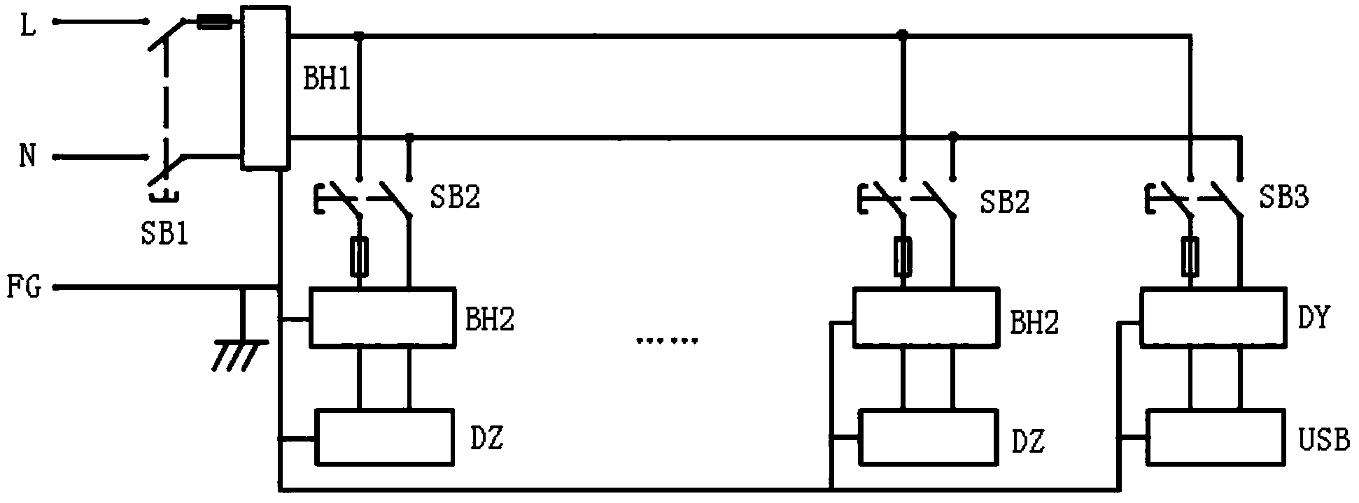
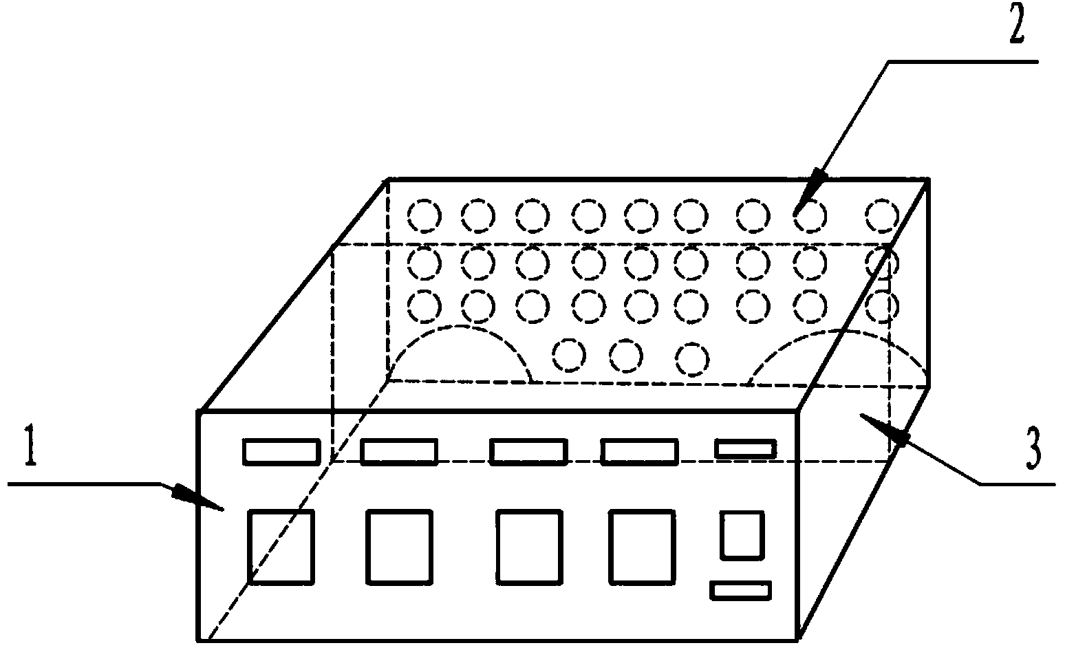
[0038] Specific implementation mode one: combine figure 1 , image 3 , Figure 4 and Figure 5Describe this embodiment, the multifunctional power supply box described in this embodiment includes a shell and a power control and protection circuit, and the power control and protection circuit includes a main power switch protection control circuit and X power control and protection output circuits with the same structure, X is an integer greater than or equal to 1;
[0039] The main power switch protection control circuit includes a first power switch control element SB1, a power fuse and a first power protection circuit BH1, and the first power switch control element SB1 and the first power protection circuit BH1 are sequentially connected in series in the multi-functional The power supply input terminal of the power supply box, the first power switch control element SB1 is the main power switch of the multi-function power supply box, and each fire wire between the first pow...
specific Embodiment approach 2
[0048] Specific implementation mode two: combination figure 1 Describe this embodiment. This embodiment is a further limitation on the multifunctional power supply box described in Embodiment 1. In this embodiment, the power control protection output circuit further includes a second power protection circuit BH2, and the second The structure of the power protection circuit BH2 is the same as that of the first power protection circuit BH1, and the second power protection circuit BH2 is connected in series with the live wire and neutral wire of the power control protection output circuit, and the second power protection circuit BH2 is located in the power fuse And between a group of power output terminals DZ.
[0049] In this embodiment, each power supply control and protection output circuit has the functions of lightning protection, current surge protection and electromagnetic compatibility protection against electromagnetic interference.
specific Embodiment approach 3
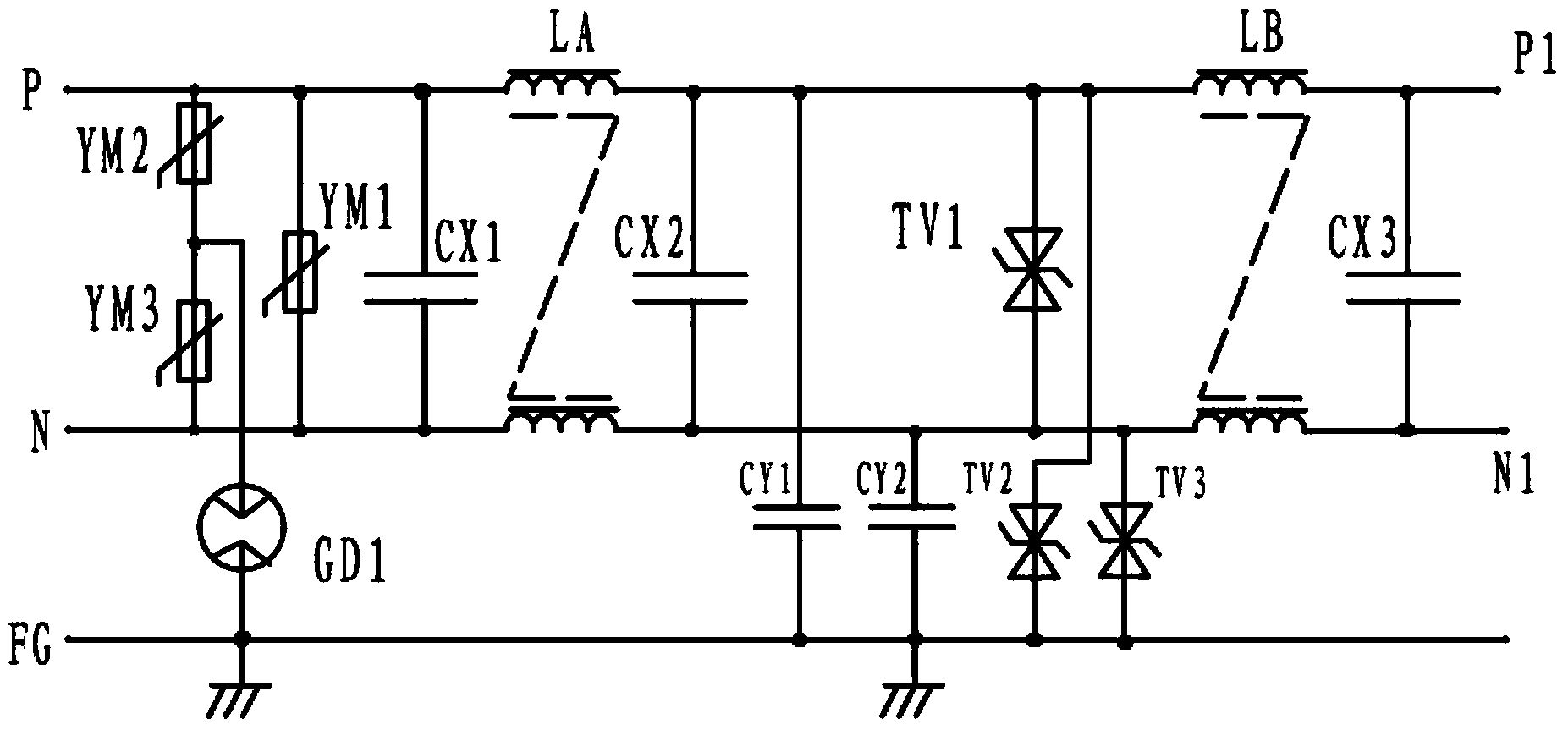
[0050] Specific implementation mode three: combination figure 2 Describe this embodiment. This embodiment is a further limitation of the multifunctional power supply box described in Embodiment 1 or 2. In this embodiment, the first power supply protection circuit BH1 includes a first piezoresistor YM1, a first Common mode inductor LA, second common mode inductor LB, first X capacitor CX1, second X capacitor CX2, third X capacitor CX3, first Y capacitor CY1, second Y capacitor CY2 and first surge absorbing diode TV1;
[0051] The two ends of the first piezoresistor YM1 are respectively connected to the live wire and neutral wire of the input end of the first power supply protection circuit BH1; the first X capacitor CX1 is connected in parallel with the first piezoresistor YM1, and one end of the first X capacitor CX1 is connected to the first One end of an inductor of the common mode inductor LA, the other end of the inductor is simultaneously connected to one end of the seco...
PUM
 Abstract
Description
Claims
Application Information
 - Generate Ideas
- Intellectual Property
- Life Sciences
- Materials
- Tech Scout
- Unparalleled Data Quality
- Higher Quality Content
- 60% Fewer Hallucinations
Browse by: Latest US Patents, China's latest patents, Technical Efficacy Thesaurus, Application Domain, Technology Topic, Popular Technical Reports.
© 2025 PatSnap. All rights reserved.Legal|Privacy policy|Modern Slavery Act Transparency Statement|Sitemap|About US| Contact US: help@patsnap.com


