Dual-operation-mode optical touch device and operation mode switching method
An operation mode, touch device technology, applied in the input/output process of data processing, instruments, electrical and digital data processing, etc., can solve problems such as easy connection of pens, inability to write normally, and poor user writing experience.
- Summary
- Abstract
- Description
- Claims
- Application Information
AI Technical Summary
Problems solved by technology
Method used
Image

Examples
Embodiment 1
[0086] This embodiment uses two infrared image sensors to realize single-point or two-point touch.
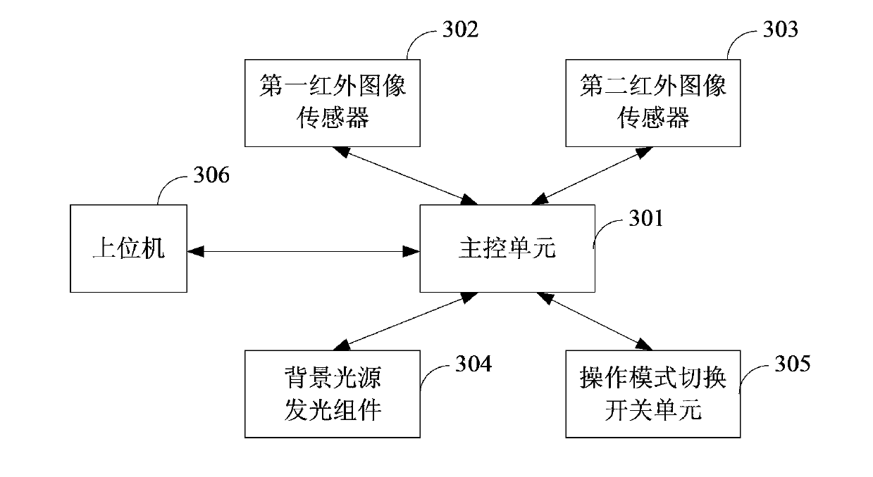
[0087] see image 3 In addition to the main control unit 301, two infrared image sensors 302, 303, and the background light source lighting assembly 304, the optical touch device in a preferred embodiment of the present invention also includes an operation mode switch unit 305 and a light source stylus ( image 3 not shown). The main control unit 301 is connected to the infrared image sensors 302 , 303 and the background light emitting component 304 respectively, and the main control unit 301 is also connected to a host computer 306 .
[0088] In practical applications, the two infrared image sensors 302 and 303 can be respectively arranged at any two adjacent corners of the screen, and the corresponding background light source light-emitting components 304 are arranged on the other three sides of the screen frame except the side where the infrared image sensor is located. on...
Embodiment 2
[0109] This embodiment also uses two infrared image sensors to realize single-point or two-point touch.
[0110] see Figure 7 , the optical touch device of the second preferred embodiment of the present invention also includes a main control unit 710, two infrared image sensors 702, 703 and a background light source lighting assembly 704, the main control unit 710 and the two infrared image sensors 702 , 703 are connected to the background light source lighting assembly 704 respectively, and also include a hardware switch 705 and a smart pen holder 706 connected to the main control unit 710 respectively, and a light source stylus ( image 3 not shown).
[0111] In this embodiment, the positions of the two infrared image sensors 702 and 703 and the background light source lighting assembly 704 are the same as those in the first embodiment, and will not be repeated here.
[0112] In this embodiment, the switching of the operation mode can be realized in four ways:
[0113] T...
Embodiment 3
[0140] In practical application, multi-touch can be realized by 3, 4 or more infrared sensors. In this embodiment, multi-touch is realized by 4 infrared image sensors.
[0141] see Figure 10 , the optical touch device of the third preferred embodiment of the present invention also includes a main control unit 110, four infrared image sensors 120, 130, 140, 150 and a background light source lighting assembly 190, the main control unit 110 and four The infrared image sensors 120, 130, 140, 150 are connected to the background light source lighting assembly 190 respectively, and also include a hardware switch 160 and a smart pen holder 170 connected to the main control unit 110, and one or more light source stylus ( image 3 not shown).
[0142] In this embodiment, the switching of the operation mode is the same as that in the second preferred embodiment, and it can also be realized in four ways, which will not be repeated here.
[0143] The four infrared image sensors 120, 130...
PUM
 Abstract
Description
Claims
Application Information
 - R&D
- Intellectual Property
- Life Sciences
- Materials
- Tech Scout
- Unparalleled Data Quality
- Higher Quality Content
- 60% Fewer Hallucinations
Browse by: Latest US Patents, China's latest patents, Technical Efficacy Thesaurus, Application Domain, Technology Topic, Popular Technical Reports.
© 2025 PatSnap. All rights reserved.Legal|Privacy policy|Modern Slavery Act Transparency Statement|Sitemap|About US| Contact US: help@patsnap.com