
A device for generating moving boundaries

A technology for generating devices and boundaries, which is used in measurement devices, fluid dynamics tests, and testing of machine/structural components. line, good repeatability

Active Publication Date: 2016-12-07
DONGHUA UNIV +1
View PDF5 Cites 0 Cited by
  • Summary
  • Abstract
  • Description
  • Claims
  • Application Information

AI Technical Summary

Problems solved by technology

[0004] The object of the present invention is to provide a flow-around experimental device with a movable boundary, which solves the problem that the existing technology cannot change the boundary and cannot realize the control of boundary deformation

Method used


Image

  • A device for generating moving boundaries
  • A device for generating moving boundaries
  • A device for generating moving boundaries

Examples


Embodiment Construction

[0021] In order to make the present invention more comprehensible, preferred embodiments are described in detail below with accompanying drawings.

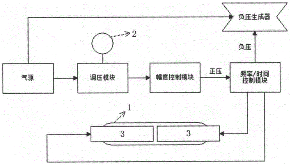
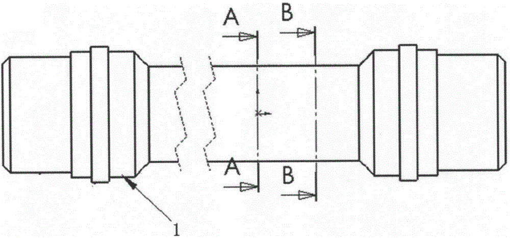
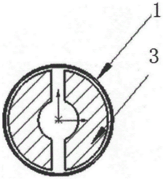
[0022] Such as figure 1 As shown, the device for generating the dynamic boundary proposed by the present invention includes an air source, a pressure regulation module, a boundary deformation amplitude control module, a boundary deformation frequency / time control module, a negative pressure generator, and a machine installed with objects of different shapes to be studied. Install device 3.

[0023] The air source can be an air compressor, which plays a role in the dynamic boundary experiment device: to ensure the formation of the dynamic boundary, and to provide gas power to the components such as the pressure regulating module, the amplitude control module and the negative pressure generator, so as to ensure the stability of the whole device. The source of gas is the guarantee for the continuous operation of the generating devic...


PUM


Abstract

The invention relates to a movable boundary generating device which comprises an air source, a boundary deformation frequency control module, a boundary deformation time control module, a boundary deformation degree control module, a negative-pressure generator and mounting devices for researched objects in different shapes. The movable boundary generating device has the advantages that movable detour flow boundaries in different shapes can be generated by the movable boundary generating device, boundary layers can be changed by the aid of the air source and the various control modules, static detour flow in different shapes can be implemented if parameters are not modified in experiment procedures, and deformation of the boundaries can be controlled if the frequency control module, the time control module and the deformation degree control module are utilized; the detour flow in the different shapes can be implemented by the aid of the different mounting devices, and accordingly detour flow with the movable boundaries can be generated.

Description

technical field [0001] The invention relates to a device for generating a moving boundary, which can study the flow phenomenon after the fluid passes through objects of different shapes (moving boundary), and produce different vortex effects after passing through the inner (outer) boundary of the device , thus forming different flow fields. Background technique [0002] The flow around cylinders and rectangular columns of various shapes and their combinations is a classic fluid mechanics problem. In real life, there are all kinds of flow-around devices such as bridge piers, aircraft wings, marine organisms, etc., and even large objects such as support columns of offshore oil collection platforms and aircraft carriers are inseparable from the category of flow-around motion. Among these flow objects, the ones with more research value are those whose boundaries change. Aquatic animals such as fish and flying animals with wings have undergone hundreds of millions of years of ev...

Claims


Application Information

Patent Timeline
Patent Type & Authority Patents(China)
IPC IPC(8): G01M10/00
Inventor 王鑫陈瑜马云驰谢锡麟麻伟巍
Owner DONGHUA UNIV
Learn More