
Attaching the blades of an axial turbocompressor to the compressor drum

A technology of axial flow turbines and blades, which is applied in the direction of machines/engines, supporting elements of blades, components of pumping devices for elastic fluids, etc., which can solve the problems of hard-to-reach clamping surfaces and complex processing, and achieve increased clearance , reduce the volume, simplify the effect of processing

Inactive Publication Date: 2014-08-06
SAFRAN AERO BOOSTERS SA
View PDF6 Cites 6 Cited by
  • Summary
  • Abstract
  • Description
  • Claims
  • Application Information

AI Technical Summary

Problems solved by technology

Clamping surfaces are relatively inaccessible due to the closed nature of the recess, complicating machining

Method used


Image

  • Attaching the blades of an axial turbocompressor to the compressor drum
  • Attaching the blades of an axial turbocompressor to the compressor drum
  • Attaching the blades of an axial turbocompressor to the compressor drum

Examples


Embodiment Construction

[0036] In the following description, the terms inner and outer relate to a position relative to the axis of rotation of the axial turbine.

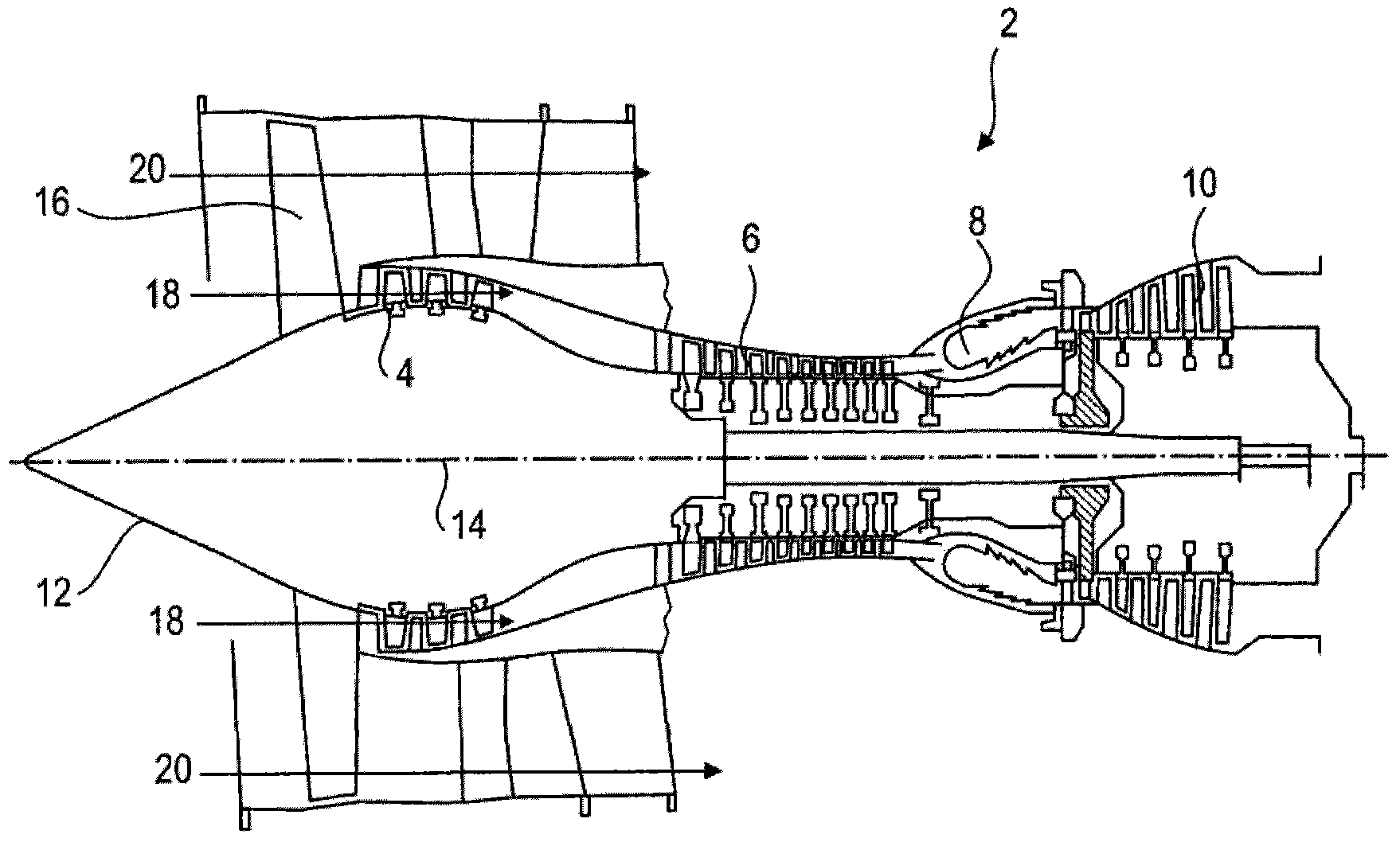
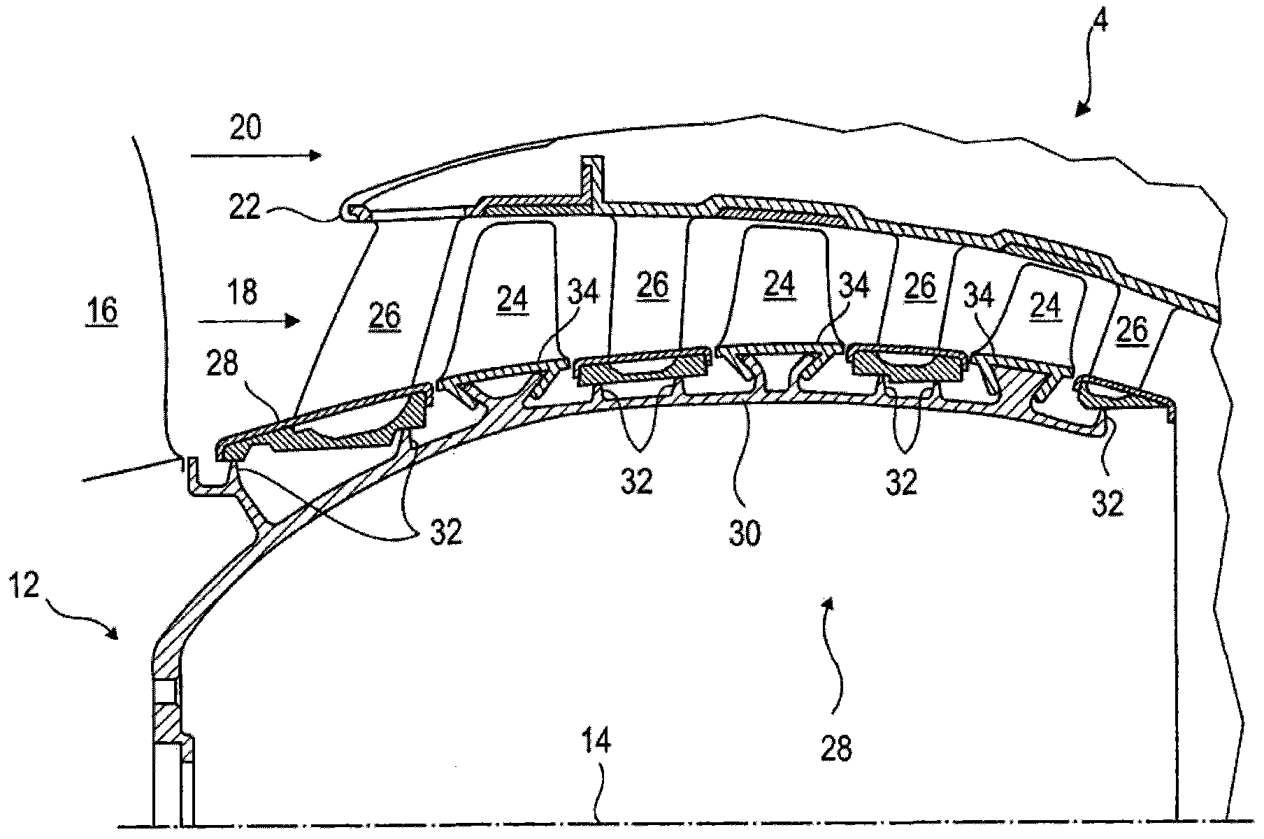
[0037] figure 1 An axial turbine is shown. In this case it is a twin-flow turbojet engine. The turbojet engine 2 comprises a first compression stage (called low pressure compressor 4 ), a second compression stage (called high pressure compressor 6 ), a combustion chamber 8 and one or more turbine stages 10 . In operation, the mechanical power of the turbine 10 is transmitted through the central shaft to the rotor 12 and drives the two compressors 4 and 6 . The reduced mechanism increases the rotational speed delivered to the compressor. Alternatively, each different turbine stage may be connected to the compressor stage by a concentric shaft. The compressor includes several rows of rotor blades associated with rows of stator blades. The rotation of the rotor 12 about its axis of rotation 14 thus generates a flow of air, compressing i...


PUM


Abstract

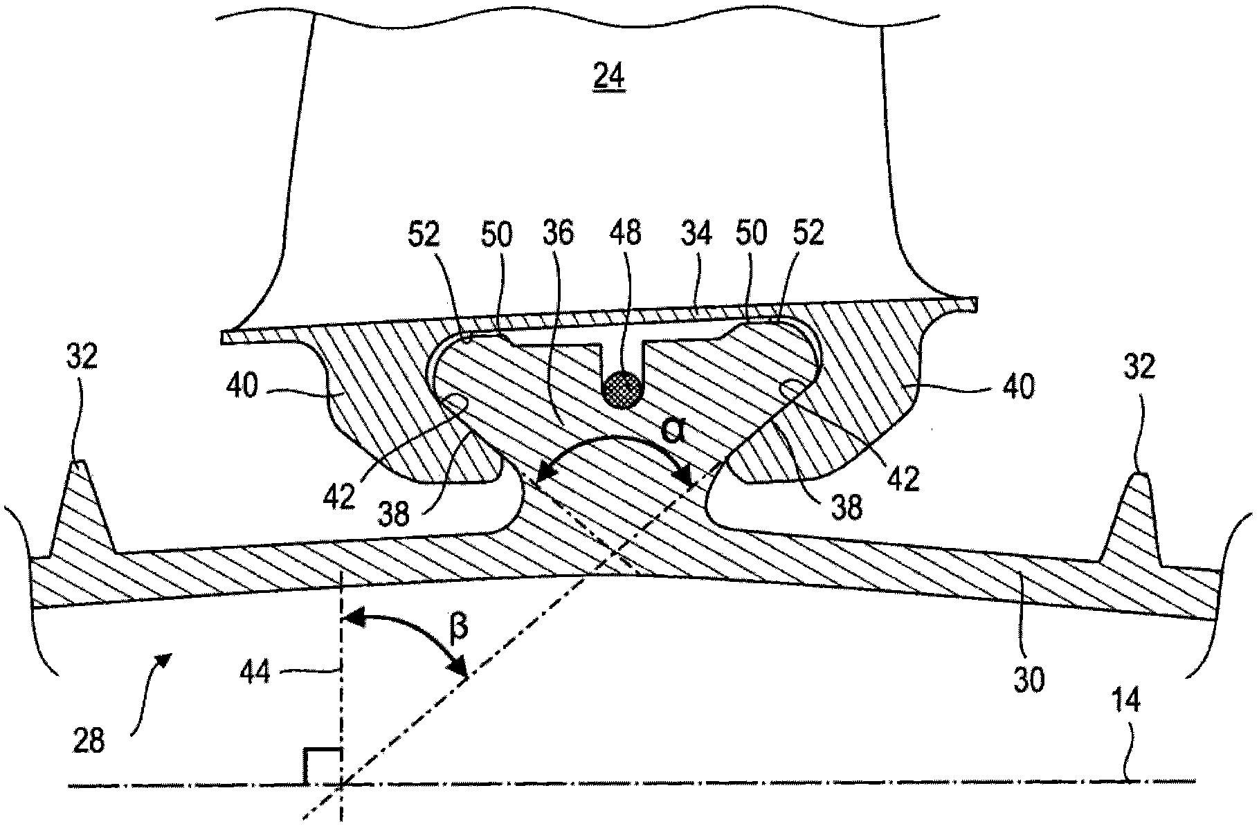
The present invention relates to the compressor drum of an axial turbomachine. The drum includes a wall of revolution that forms a hollow body. The wall includes two annular retaining surfaces of the blades which mate with corresponding retaining surfaces of the said blades. These surfaces are generally directed away from one another to form a profile which diverges as its distance radially from the outer surface of the wall increases. The retaining surfaces of the drum may be formed on an outer annular body or on inclined annular flanges.

Description

technical field [0001] The present invention relates to a bladed drum of an axial flow compressor. More particularly, the invention relates to a drum on which rotor blades are connected by positive material contacts. The invention also relates to a turbine equipped with such a drum. Background technique [0002] Preferably, the axial turbocompressor has several compression stages. Each compression stage includes an annular row of rotor blades and an annular row of stator blades. The compressor rotor is formed from a drum with axially symmetrical walls, which results in a lightweight and economical monolithic element. [0003] The drum has a substantially annular thin wall to which the rotor blades are directly connected. There are several schemes for accomplishing this. The blades may be welded to holes in the drum wall, or the blade roots may be inserted into axial slots cut into the drum. [0004] Alternatively, the drum may be provided with an annular recess within ...

Claims


Application Information

Patent Timeline
Patent Type & Authority Applications(China)
IPC IPC(8): F04D29/32F04D29/34F02K3/06F02K3/00
CPCF01D5/02F01D5/06F01D5/3046F01D11/02F01D11/122F05D2250/38F01D5/066
Inventor C·雷米
Owner SAFRAN AERO BOOSTERS SA
Learn More