Eureka AIR delivers breakthrough ideas for toughest innovation challenges, trusted by R&D personnel around the world.

A hydraulic controller for common rail fuel injector with middle hole pressure accumulation

A common rail injector and pressure accumulator technology, which is applied in the direction of machines/engines, fuel injection devices, engine components, etc., can solve the problems of high cleanliness requirements, unfavorable popularization and application, and high processing costs, so as to reduce return Oil back pressure sensitivity, improved fuel injection accuracy, and reduced processing difficulty

Active Publication Date: 2016-02-17
钧风电控科技泰州有限责任公司
View PDF6 Cites 8 Cited by
  • Summary
  • Abstract
  • Description
  • Claims
  • Application Information

AI Technical Summary

Problems solved by technology

However, in practical applications, due to its very complex structure, high processing costs, and high requirements for cleanliness, it is not conducive to large-scale promotion and application in the domestic market.

Method used


Image

  • A hydraulic controller for common rail fuel injector with middle hole pressure accumulation

Examples


Embodiment Construction

[0018] The present invention will be further described below in conjunction with the accompanying drawings.

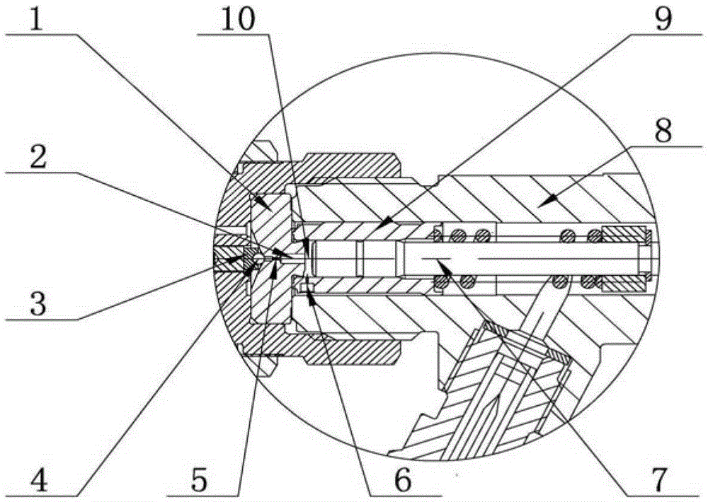
[0019] like figure 1 As shown, the present invention includes a conical ball valve switch valve, a control sleeve 9, a control plunger 7 and a spring, wherein the control sleeve 9, the control plunger 7 and the spring are all arranged in the middle hole of the fuel inlet end of the injector body 8 In the pressure accumulator chamber, one end of the control plunger 7 is inserted in the control sleeve 9 and is slidably connected with the control sleeve 9. The other end of the control plunger 7 is sleeved with a spring, and the two ends of the spring are respectively controlled by The counterbore at one end of the sleeve 9 is positioned with the spring seat arranged at the other end of the control plunger 7 . The conical ball valve type on-off valve is arranged at the end of the oil inlet end of the injector body 8 and accommodated in a nut threadedly connected with the ...


PUM


Abstract

The invention belongs to the technical field of center hole pressure accumulation type common rail fuel injectors, and particularly relates to a hydraulic controller of a center hole pressure accumulation type common rail fuel injector. The hydraulic controller comprises a cone ball valve type switching valve, a control sleeve, a control plunger and a spring, the control sleeve, the control plunger and the spring are all arranged in a center hole accumulation cavity at the fuel inlet end of a fuel injector body, one end of the control plunger is inserted into the control sleeve and slidingly connected with the control sleeve, the other end of the control plunger is sleeved with the spring, and two ends of the spring are respectively positioned via one end of the control sleeve and a spring seat arranged at the other end of the control plunger. The cone ball valve type switching valve is arranged on the end portion of the fuel inlet end of the fuel injector body, accommodated in a nut in threaded connection with the end portion of the fuel inlet end of the fuel injector body, and hermetically connected with the other end of the control sleeve. A hydraulic control cavity is arranged between the control plunger and the cone ball valve type switching valve, a fuel inlet orifice communicating the hydraulic control cavity and the middle hole pressure accumulation cavity is formed in the control sleeve, and a fuel outlet orifice communicating the hydraulic control cavity and a low pressure cavity is formed in the cone ball valve type switching valve. The hydraulic controller is simple in structure, low in processing cost and low in requirement on cleanliness of fuel.

Description

technical field [0001] The invention belongs to the technical field of a middle-hole pressure-accumulating common-rail fuel injector, in particular to a hydraulic controller of a middle-hole pressure-accumulating common-rail fuel injector. Background technique [0002] The high-pressure common rail fuel injection system for diesel engines was developed to cope with emissions above Euro III, and has become the mainstream technology of diesel engine fuel systems. Since Denso Corporation of Japan successfully applied the high-voltage common rail system to trucks in 1995, this technology has been monopolized by several international companies such as Bosch of Germany, Denso of Japan, Delphi of the United States and Continental of Germany. At present, traditional mechanical fuel systems are still widely used in the domestic market, which urgently needs to be upgraded to meet the emission requirements of China III and above. [0003] At present, the patent of the common rail syst...

Claims


Application Information

Patent Timeline
Patent Type & Authority Patents(China)
IPC IPC(8): F02M47/02
Inventor 臧广辉李波卫忠星王雷解芳赵莹邢雨韩宜龙康凯
Owner 钧风电控科技泰州有限责任公司
Why Eureka
Eureka Blog
Learn More