
Filling-capping integrated machine

An all-in-one machine, filling and rolling technology, applied in bottling machines, liquid bottling, liquid treatment, etc., can solve the problems of high equipment cost, large space occupation, and high energy consumption, and achieve simple and convenient adjustment, compact structure, and space occupation small effect

Active Publication Date: 2014-08-06
TRUKING TECH LTD
View PDF8 Cites 18 Cited by
  • Summary
  • Abstract
  • Description
  • Claims
  • Application Information

AI Technical Summary

Problems solved by technology

[0002] The filling and rolling machine mainly includes bottle conveying device, filling machine, stoppering machine, capping machine and capping machine, etc. The bottle conveying device conveys the bottle through the filling station, stoppering station, and capping station in sequence. and capping station, and finally complete the filling and rolling operation of the bottle body. The filling and rolling integrated machine in the prior art usually uses a synchronous belt bottle conveying device driven by a servo motor to transport the bottle body, and uses a multi-needle filling machine, The disc-type stoppering machine and the disc-type capping machine can fill, stopper and cap the bottle body, and can complete the filling and rolling of the bottle body in batches at the same time, but there are problems of large space occupation, high equipment cost and difficult maintenance , and when conveying bottles of different specifications, multiple parts must be replaced. If the existing synchronous belt bottle conveying device is used for filling and rolling experiments of small batches and multi-standard bottles, the operation is complicated and the output is high, which may easily cause Waste of materials, high energy consumption, etc.

Method used


Image

  • Filling-capping integrated machine
  • Filling-capping integrated machine
  • Filling-capping integrated machine

Examples


Embodiment Construction

[0028] The present invention will be further described in detail below in conjunction with the accompanying drawings and specific embodiments.

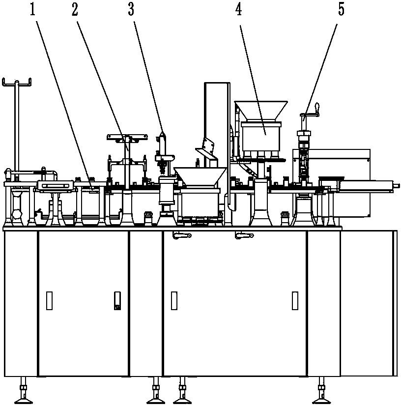
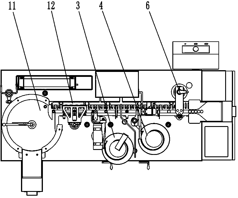
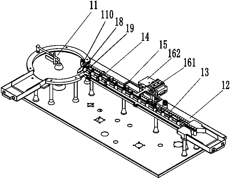
[0029] Figure 1 to Figure 10 An embodiment of the integrated filling and rolling machine of the present invention is shown. The integrated filling and rolling machine includes a bottle conveying device 1, a filling device 2, a stoppering device 3, a cap hanging device 4 and a capping device 5, and the filling device 2 , the stoppering device 3, the cap hanging device 4 and the capping device 5 are sequentially arranged along the bottle conveying direction of the bottle conveying device 1, and it is characterized in that: the bottle conveying device 1 includes an unscrambling disc assembly 11 and is docked with the unscrambling disc assembly 11 The bottle shifting assembly 12, the bottle shifting assembly 12 includes a bottom rail 13 for holding bottles, a bottle shifting plate 14, a bottle shifting bracket 15 and a bottle shifting pl...


PUM


Abstract

The invention discloses a filling-capping integrated machine which comprises a bottle body conveying device, a filling device, a plug adding device, a cap handing device and a capping device, wherein the filling device, the plug adding device, the cap handing device and the capping device are sequentially arranged in the bottle conveying direction of the bottle body conveying device; the bottle body conveying device comprises a bottle unscramblingdisc component and a bottle moving component butted with the bottle unscrambling disc component; the bottle moving component comprises a bottle supporting bottom track, a bottle stirring plate, a bottle stirring support and a bottle stirring plate driving component; the bottle stirring plate is arranged on the bottle stirring support and above the bottle supporting bottom track; the bottle stirring support is connected with the bottle stirring plate driving component; the bottle feeding direction of the bottle unscramblingdisc component is perpendicular to the bottle supporting bottom track. The filling-capping integrated machine disclosed by the invention has the advantages that the structure is compact, the occupied space is small, the operation is convenient and the cost is reduced.

Description

technical field [0001] The invention relates to medicine filling equipment, in particular to a filling and rolling integrated machine. Background technique [0002] The filling and rolling machine mainly includes bottle conveying device, filling machine, stoppering machine, capping machine and capping machine, etc. The bottle conveying device conveys the bottle through the filling station, stoppering station, and capping station in sequence. and capping station, and finally complete the filling and rolling operation of the bottle body. The filling and rolling integrated machine in the prior art usually uses a synchronous belt bottle conveying device driven by a servo motor to transport the bottle body, and uses a multi-needle filling machine, The disc-type stoppering machine and the disc-type capping machine can fill, stopper and cap the bottle body, and can complete the filling and rolling of the bottle body in batches at the same time, but there are problems of large space...

Claims


Application Information

Patent Timeline
Patent Type & Authority Applications(China)
IPC IPC(8): B67C7/00B67C3/24B67B1/04B67B3/00
Inventor 莫文勇
Owner TRUKING TECH LTD
Learn More