Adjustable substrate lock and lock adjustment equipment
A technology for substrate locking and adjusting equipment, which is applied to lighting and heating equipment, conveyor objects, furnaces, etc., can solve the problems of limited panel size, inconsistent size, and difficult control of manual adjustment accuracy, and achieves simple structure and precise adjustment. Effect
- Summary
- Abstract
- Description
- Claims
- Application Information
AI Technical Summary
Problems solved by technology
Method used
Image
Examples
Embodiment 1
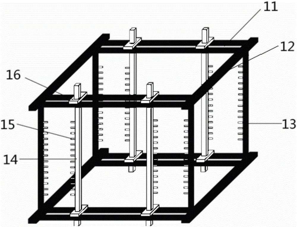
[0034] Such as figure 1 As shown, the adjustable base plate clamp (hereinafter referred to as the clamp) of this embodiment includes at least two sets of vertical beams, each set of vertical beams includes two vertical beams 13 arranged in parallel, and the upper edges of the two vertical beams 13 in each group A number of supporting sheaths 15 of equal height and predetermined spacing are provided in the vertical direction, and the two ends of the two vertical beams 13 in each set of vertical beams are respectively connected by two beam structures to form at least two planar quadrilateral frames. Between the two beam structures, at least one moving beam 14 parallel to the vertical beam 13 and capable of moving laterally along the beam structure is provided, and the moving beam 14 is vertically provided with a support sheath 15 on the vertical beam. Support sheaths 15 of equal height and predetermined spacing. The support sheath 15 is used to support the substrate.
[0035] ...
Embodiment 2
[0050] Such as Figure 7a As shown, the structure of the adjustable cassette in this embodiment is basically similar to the structure of the cassette in Embodiment 1. The difference lies in the structure of the beam and the structure of the moving beam. The position of the double beams 11 in Embodiment 1 is Become " T " or " L " font crossbeam 71 in the scheme 2. Specific as Figure 7b As shown, the crossbeam 71 has a crossbeam structure with a right-angle groove, and the two crossbeams 71 are arranged mirror-image-symmetrically, and the right-angle groove is oppositely arranged, that is, the moving beam 14 can be taken out from the right-angle groove along the direction of the arrow, or in the opposite direction. Put it into the right angle groove and fix it. The material is also metal. The moving beam 14 is a magnetic material that is attracted to the beam 71. Both ends are located in a right-angle groove, and its length is slightly smaller than the gap between the upper ...
PUM
 Abstract
Description
Claims
Application Information
 - R&D
- Intellectual Property
- Life Sciences
- Materials
- Tech Scout
- Unparalleled Data Quality
- Higher Quality Content
- 60% Fewer Hallucinations
Browse by: Latest US Patents, China's latest patents, Technical Efficacy Thesaurus, Application Domain, Technology Topic, Popular Technical Reports.
© 2025 PatSnap. All rights reserved.Legal|Privacy policy|Modern Slavery Act Transparency Statement|Sitemap|About US| Contact US: help@patsnap.com


