
Push type liquid pump

A liquid pump, push-type technology, applied in the field of liquid pumps, can solve problems such as deformation of the ball or valve seat, difficulty in control, and difficulty in proper sealing of one-way ball valves, and achieve the effect of avoiding deformation and failure

Active Publication Date: 2017-11-17
丁要武
View PDF15 Cites 0 Cited by
  • Summary
  • Abstract
  • Description
  • Claims
  • Application Information

AI Technical Summary

Problems solved by technology

First of all, this structure requires very high manufacturing precision to ensure that the ball of the one-way ball valve can be accurately pressed against the valve seat when the pressure head is in the lock position; Proper sealing to the ball valve, because the pressure head is locked to the cylinder head in a threaded manner, the nature of the threading method makes it difficult to control the force applied to the one-way ball valve, making it difficult for the user to achieve a proper seal
Secondly, since the one-way ball valve will be under pressure for a long time in the state of the head of the pressure head, it is easy to cause deformation of the ball or valve seat, resulting in the one-way ball valve not working properly during the use of the liquid pump in the future.

Method used


Image

  • Push type liquid pump
  • Push type liquid pump
  • Push type liquid pump

Examples


Embodiment Construction

[0033]First of all, by the way, the "up" and "down" mentioned in this article are determined relative to the liquid pump being placed in a vertical orientation (that is, the liquid pump is set so that its axis direction is consistent with the vertical direction) .

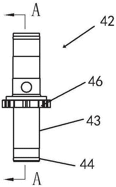
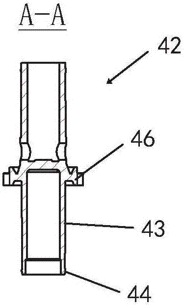
[0034] see figure 1 - 4b, which shows a first embodiment of the invention. The liquid pump mainly includes a pressure head 10 with an outlet, a cylinder 20 defining a liquid storage tank 30, and is slidably arranged in the liquid storage tank 30 along the axial direction and connected with the pressure head 10 so as to be able to move up and down in the liquid storage tank 30. The reciprocating piston assembly 40, the helical metal compression spring 50 (that is, the elastic return device) arranged in the liquid storage tank 30 for applying an upward bias to the piston assembly 40 in the axial direction, and the The lower one-way valve 60 at the bottom of 30 is used to control the one-way communication between t...


PUM


Abstract

The invention provides a pressing liquid pump. The liquid pump includes a pressure head, a liquid storage tank formed by a cylinder, a piston assembly slidably arranged in the liquid storage tank along the axial direction and connected with the pressure head to reciprocate up and down in the liquid storage tank, and a piston assembly arranged in the liquid storage tank. There is an elastic return device in the tank for biasing the piston assembly in the axial direction, and a lower one-way valve arranged at the bottom of the storage tank for controlling the one-way communication between the storage tank and the interior of the container. The ram is positionable relative to the cylinder in a lock position in which the ram is locked to the cylinder against reciprocating movement of the piston assembly within the reservoir. According to the present invention, the liquid pump further includes a sealing mechanism for blocking the communication between the liquid storage tank and the lower one-way valve when the pressure head is at the lock head position. The present invention can effectively prevent the liquid product in the container from escaping from the lower one-way valve and contact the easy-to-oxidize parts such as the elastic reset device in the liquid storage tank before the liquid pump is used for the first time, so as to avoid the product from being damaged during storage. oxide contamination.

Description

technical field [0001] The invention relates to the field of liquid pumps, in particular to a push-type liquid pump with an elastic reset device. Background technique [0002] The push-type liquid pump is generally installed at the opening of the container, and is used for pumping and distributing the liquid product in the container out of the container through a manual pressing operation by a user for use. This type of liquid pump usually has an elastic reset device, which is used to return the pump head to its original position after the user removes the downward pressure on the pump head, and at the same time, the liquid product in the container is sucked during the reset process of the pump head. into the reservoir of the liquid pump for the next pump pressure dispense. Currently on the market, there are push-type liquid pumps with elastic return devices (usually metal springs), such as Figure 9 and 10 As shown, the elastic return device 250 is mostly arranged in the ...

Claims


Application Information

Patent Timeline
Patent Type & Authority Patents(China)
IPC IPC(8): B65D47/34
Inventor 丁要武
Owner 丁要武
Learn More