
Surrounding type blowing dust removal device

An ash cleaning device and a wrap-around technology, which are used in the separation of dispersed particles, chemical instruments and methods, and filtration of dispersed particles, etc., can solve problems such as unfavorable work efficiency, loss, pollution and purification of gas, and achieve ingenious and reasonable structural design. The effect of tightness and long service life

Active Publication Date: 2014-08-06
HENAN DRAGON INTO COAL TECH CO LTD
View PDF7 Cites 5 Cited by
  • Summary
  • Abstract
  • Description
  • Claims
  • Application Information

AI Technical Summary

Problems solved by technology

[0002] At present, high-temperature dust-containing gases are often produced in chemical, petroleum, metallurgical and other industries. Since different processes need to remove dust from high-temperature dust-containing gases to achieve gas-solid separation and gas purification, it is often used to filter through the filter element in the dust collector. Gas-solid separation, the filtered and purified dust-containing gas enters the clean air chamber, and the dust is filtered and left in the dust removal chamber of the dust collector and deposited into the ash hopper, while the filter element used in the dust collector will absorb a large number of particles on its outer surface during the dust removal process Dust, as the dust continues to increase, it will affect the filtration quality, so it is necessary to remove the dust accumulated on the surface of the filter element. Now the blowing pipe is commonly used to achieve reverse cleaning, but the result of back blowing will inevitably make the purified air again. Entering the space before purification, since the amount of purification gas used for each injection is relatively large, the second filtration can only be repurified, which is not conducive to improving work efficiency, and it is necessary to increase the gas pressure boosting equipment
In addition, because the tubular nozzle can only clean the part of the filter element corresponding to the nozzle, the nozzle cannot change the direction of the blowback, and there are dead corners during the nozzle that are not easy to clean, and the unfavorable accumulation of the nozzle will become more solid and difficult to remove, so it cannot be easily cleaned. Good and thorough dust removal; some manufacturers also design to use mechanical dust removal devices, such as installing brushes at the front of the manipulator, or mechanical oscillation methods, but not only the structure is complicated, but also the filter element of the dust collector is easy to be damaged due to poor action consistency, and the dust enters after the filter element is damaged. The clean air chamber of the dust collector will bring the polluted and purified gas into the subsequent process, causing great losses

Method used


Image

  • Surrounding type blowing dust removal device
  • Surrounding type blowing dust removal device
  • Surrounding type blowing dust removal device

Examples


Embodiment 1

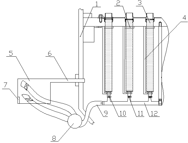
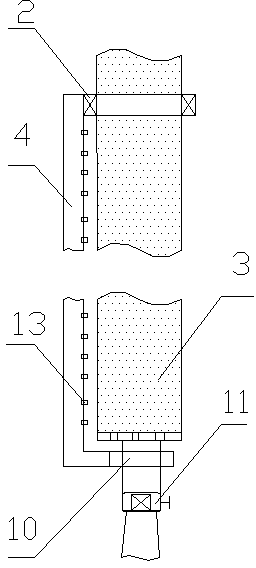
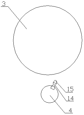
[0028] Embodiment one: if figure 1 , figure 2 and image 3 Shown, a kind of encircling blowing soot cleaning device, it comprises blowing gas conveying pipe 9, control valve 11, swivel joint 10 and blowing pipe 4, and described blowing pipe 4 is provided with several nozzles 13, and described control valve 11 The rotary joint 10 is arranged at the lower part of the filter element 3 of the dust collector.

[0029] The blowing pipe 4 is L-shaped, the upper part of the blowing pipe 4 is connected with the upper part of the filter core 3 of the dust collector through the bearing 2 , and the lower part is connected with the control valve 11 through the rotary joint 10 .

[0030] The filter element 3 is a stainless steel filter element.

[0031] The blowing gas delivery pipe 9 is connected to the cooling device 5, and the cooling device 5 is connected to the dust-laden gas inlet pipe 6 of the dust collector.

[0032] The blowing gas delivery pipe 9 is provided with a pressure ...

specific Embodiment 2

[0038] The difference from Embodiment 1 is that the cooling device 5 is an air cooler.

specific Embodiment 3

[0039] The difference from Embodiment 1 or 2 is that: the pressure raising device 8 is an air compressor.

[0040] In order to better describe this device, its mechanism principle is as follows: the present invention includes a series-connected blowing gas delivery pipe, a control valve, a rotary joint and a blowing pipe, and the blowing gas delivery pipe is provided with a pressure raising device, which can realize The blowing of low-temperature and high-pressure gas makes the stainless steel filter core shrink and remove dust. The lower part of the blowing pipe is connected to the rotary joint, and the rotary joint is connected to the control valve, and the angle between the opening direction of the nozzle and the diameter direction of the filter core is cleverly used. The characteristics make it possible not only to blow the gas on the surface of the filter element, but also to realize its high-speed rotation around the filter element, so that the cooling gas can quickly coo...


PUM

PropertyMeasurementUnit
Angleaaaaaaaaaa

Abstract

The invention discloses a surrounding type blowing dust removal device. The surrounding type blowing dust removal device comprises a blowing gas delivery pipe, a control valve, a rotating joint and a blowing pipe, wherein a plurality of nozzles are arranged on the blowing pipe; the control valve is arranged at the lower part of a filter element of a dust collector through the rotating joint. The heat-expansion and cold-contraction characteristic of metal is utilized, dusty gas is taken as gas for dust removal, and gas back spraying rotation is adopted, so that dust removing is well realized, the cost is low, the equipment is safe and reliable and long in operation cycle, the dust removal efficiency of the filter element is improved by more than 5%, and the operating cost is reduced by 10%; the surrounding type blowing dust removal device has excellent economic benefit, develops a new way in the aspect of dust removal for the filter element, and has excellent popularization and application value.

Description

technical field [0001] The invention belongs to the technical field of jet dust removal equipment, in particular to a surrounding jet dust removal device. Background technique [0002] At present, high-temperature dust-containing gases are often produced in chemical, petroleum, metallurgical and other industries. Since different processes need to remove dust from high-temperature dust-containing gases to achieve gas-solid separation and gas purification, it is often used to filter through the filter element in the dust collector. Gas-solid separation, the filtered and purified dust-containing gas enters the clean air chamber, the dust is filtered and left in the dust removal chamber of the dust collector, and deposited into the ash hopper, and the filter element used in the dust collector will absorb a large number of particles on its outer surface during the dust removal process Dust, as the dust continues to increase, it will affect the filtration quality. Therefore, it is...

Claims


Application Information

Patent Timeline
IPC IPC(8): B01D46/00
Inventor 朱书成赵家亮李金峰庞志峰
Owner HENAN DRAGON INTO COAL TECH CO LTD
Learn More