
Connector and fixing structure for fixing connector to support member

A technology for supporting parts and connectors, which is applied to the installation of connecting parts, parts of connecting devices, and connection, etc. It can solve the problems of insufficient joint force and inability to position, and achieve size reduction, work improvement, and small contact area. Effect

Active Publication Date: 2016-07-06
YAZAKI CORP
View PDF6 Cites 1 Cited by
  • Summary
  • Abstract
  • Description
  • Claims
  • Application Information

AI Technical Summary

Problems solved by technology

More specifically, the engaging force of the fitting engagement of the engaging piece 234 and the protrusion 224 fluctuates in the combined connector 201, and the engaging force after combining the connectors 220 and 230 is not large enough.
For this reason, connectors 220 and 230 move, and therefore cannot be positioned

Method used


Image

  • Connector and fixing structure for fixing connector to support member
  • Connector and fixing structure for fixing connector to support member
  • Connector and fixing structure for fixing connector to support member

Examples


Embodiment Construction

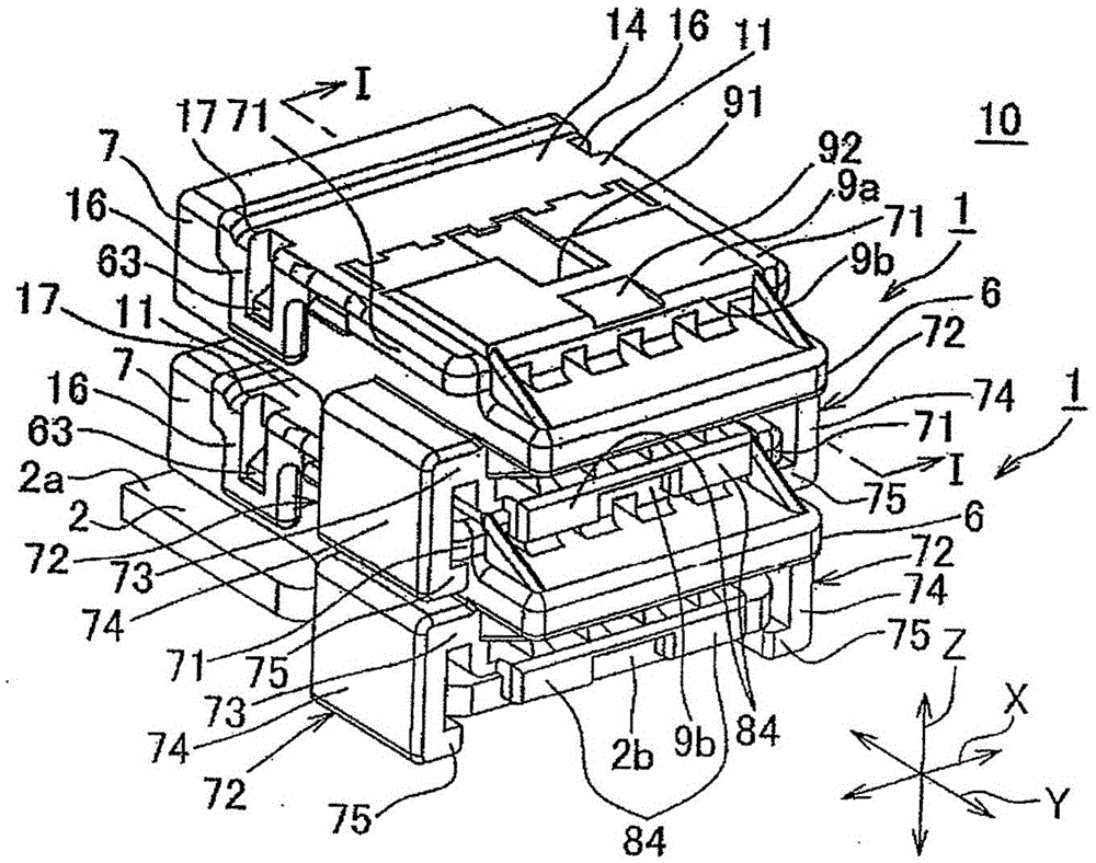
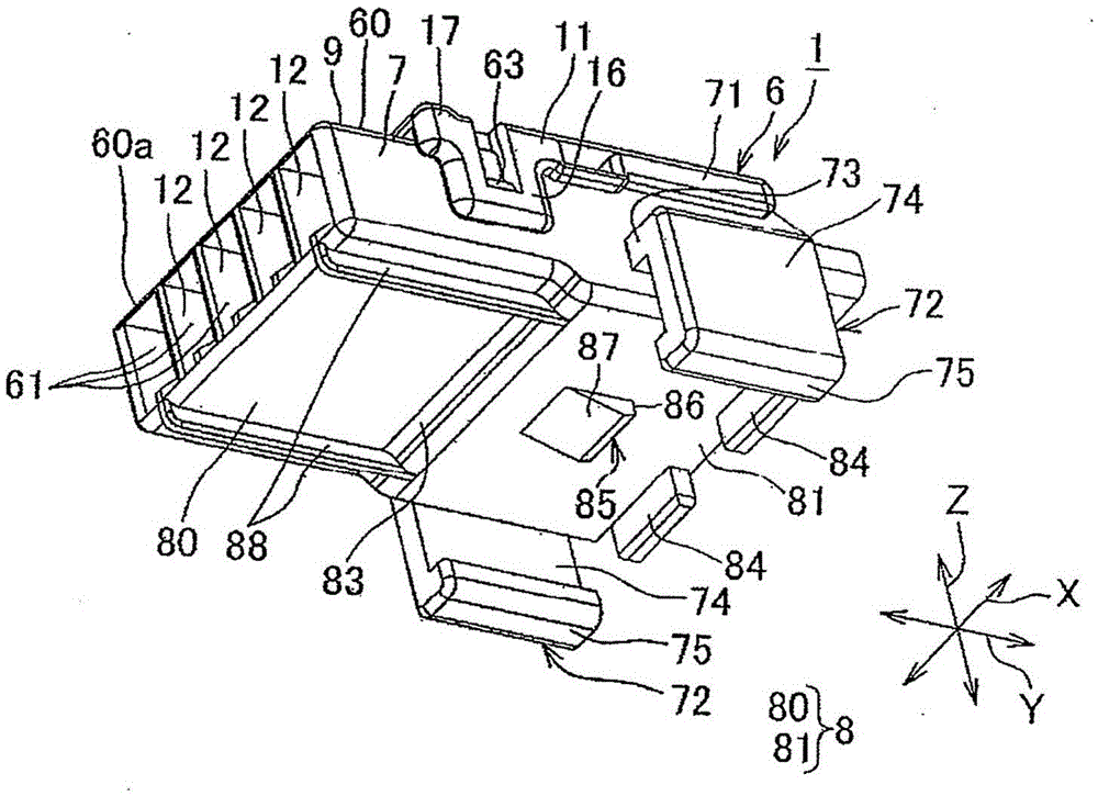
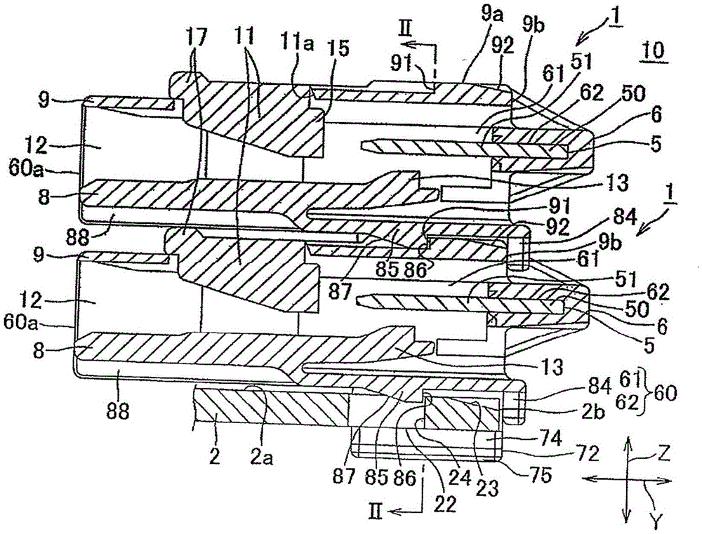
[0066] will refer to figure 1 to 6 explain the connector according to the embodiment of the present invention and the fixing structure for fixing the connector to the supporting member.

[0067] Such as Figure 10 As shown, the fixing structure 10 for fixing the connector to the supporting part has: at least one connector (in this embodiment, two connectors are provided); 1 supporting part; strap clamping device 3, the strap clamping device 3 is used to fix the connector 1 to the bracket 2. Bracket 2 is part of the vehicle. That is, the fixing structure 10 is a structure for fixing at least one connector 1 to a vehicle. The band clamping device 3 corresponds to a "binding member" described in the claims.

[0068] Connector 1 will be attached to the Figure 5 The plurality of female terminal portions of the terminals of the plurality of electric wires 4 are shown to be electrically connected to each other. Such as figure 2 As shown, connector 1 has: bus bar 5 (see im...


PUM


Abstract

The present invention provides a connector and a fixing structure for fixing the connector to a supporting member. The connector has a housing including a plurality of terminal receiving portions. The housing has a pair of rail portions projecting from both side walls of the housing, a pair of arm portions vertically extending from the both side walls downward and formed in U-shape, and a stopper projecting from a bottom wall of the housing. When the housings having the same structure are laminated up and down, the pair of the rail portions of the lower housing are respectively sandwiched between the pair of the arm portions of the upper housing, and the stopper of the upper housing abuts on a rear end of an upper wall of the lower housing.

Description

technical field [0001] The present invention relates to a connector having: a housing in which a terminal accommodating portion is arranged; and a fixing structure for fixing the connector to a supporting member. Background technique [0002] Figure 7 is a side view showing a conventional fixing structure for fixing a connector to a supporting member. Figure 8 yes Figure 7 An exploded perspective view of the conventional fixed structure shown. Figures 9A to 9D is to show the Figure 7 An illustration of the process of securing the shown connector to the bracket. Such as Figure 7 with 8 As shown, a conventional fixing structure 110 for fixing a connector to a supporting member has: a housing 102 in which a plurality of terminal receiving parts 103 are arranged; two connectors 101, and the two connectors 101 are mutually stacking; a bracket 104 as a supporting member for fixing the two connectors 101 thereto; and a strap clamp 105 as a binding member. The two housings...

Claims


Application Information

Patent Timeline
Patent Type & Authority Patents(China)
IPC IPC(8): H01R13/506H01R13/514H01R13/73
CPCH01R13/506H01R13/514H01R13/73
Inventor 岩泽英彦池元进一
Owner YAZAKI CORP
Learn More