
Micro-grid dynamic self-adapting relay protection method and self-adapting protection device

A dynamic self-adaptive, relay protection technology, applied in emergency protection circuit devices, electrical components, etc., can solve the problems of malfunction of protection devices, influence of relay protection of distribution network, voltage drop of inverter terminals, etc. The effect of malfunction and improved availability

Active Publication Date: 2014-07-30
SHANGHAI ELECTRICGROUP CORP
View PDF1 Cites 21 Cited by
  • Summary
  • Abstract
  • Description
  • Claims
  • Application Information

AI Technical Summary

Problems solved by technology

In the fault analysis of the traditional power grid, it is often regarded as an infinite source. When a short-circuit fault occurs, the fault current can be more than ten times the normal current; while the inverter is a constant current source. When a short-circuit fault occurs when it is connected to the grid, the output current of the inverter is only increases slightly and remains stable, but the voltage at the inverter terminal decreases significantly, which affects the conventional distribution network relay protection
Prone to misoperation of protective devices, refusal to operate and unsuccessful reclosing
[0004] There are three problems in the current micro-grid relay protection design: 1. It is increasingly difficult to meet the requirements of the traditional relay protection mode of "pre-setting, real-time action, and regular inspection", and the protection cannot be foreseen in the design process. For all system conditions, the changes of the system should be considered to realize the self-adaptive setting of the protection
2. When the microgrid system is in a tense state, the misoperation of the protection will make the system worse, which will lead to the repeated start and stop of the distributed power supply
In many cases, due to manpower shortage or difficulty in planning and other reasons, the relay protection setting inspection cannot be carried out in accordance with the regulations, and some relay protection setting values ​​have reached a critical state and have not been noticed by engineers.

Method used


Image

  • Micro-grid dynamic self-adapting relay protection method and self-adapting protection device
  • Micro-grid dynamic self-adapting relay protection method and self-adapting protection device
  • Micro-grid dynamic self-adapting relay protection method and self-adapting protection device

Examples


Embodiment Construction

[0022] The present invention will be further described below in conjunction with accompanying drawing.

[0023] Microgrid dynamic adaptive protection refers to the system relay protection setting or design considering system changes, by adjusting some settings in the protection, adopting appropriate and optimized protection responses, so that the protection adapts to the load, microgrid operation mode or fault The system changes caused by other situations can improve the relay protection performance of the microgrid system.

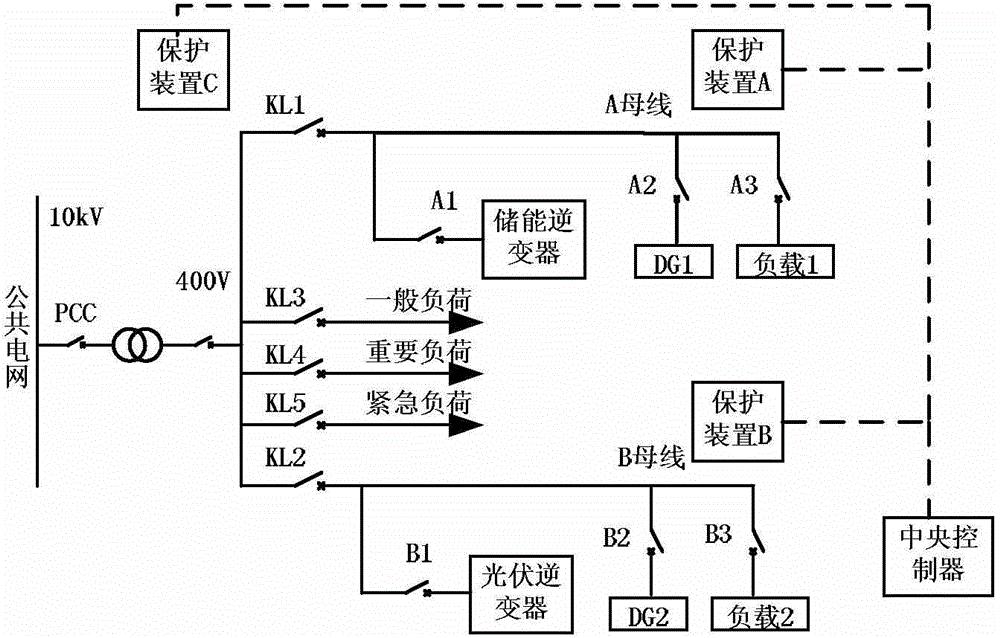
[0024] One of the micro-grid dynamic adaptive relay protection methods of the present invention is based on a central controller and several adaptive protection devices distributed at each key protection point of the micro-grid, such as figure 1 As shown, the adaptive protection devices arranged at each key protection point interact with the central controller through the advanced data communication technology inside the microgrid. The protection devices...


PUM


Abstract

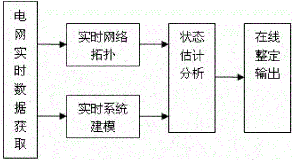
The invention discloses a micro-grid dynamic self-adapting relay protection method which is based on a central control unit and multiple self-adapting protection devices. The method comprises the steps of collecting analog quantity and digital quantity information in a micro-grid in real time, carrying out full network connectivity judgment on line, and obtaining a real-time network topology structure; establishing calculation modules for distributed power sources, branch subsystems and loads inside and outside the micro-grid, and establishing a state estimation module; transmitting calculated micro-grid operation state information to all the self-adapting protection devices, and matching area protection constant values after output optimization according to a setting valve rule library. Relay protection of a system can be achieved in grid connection, intelligent protection can be achieved in isolated grid operation, misoperation and operation failure of the system can be reduced, the usability of the micro-grid system can be improved. The invention further provides the self-adapting protection device and an internal integration setting valve rule library, protection, measurement and control are integrated, and real-time protection and control of regions can be achieved well.

Description

technical field [0001] The invention relates to the field of low-voltage micro-grid relay protection, in particular to a micro-grid dynamic adaptive relay protection method and an adaptive protection device used in the method. Background technique [0002] Like conventional power systems, microgrids also need to meet the requirements of safety and stability, and their relay protection principles must meet reliability, quickness, sensitivity and selectivity. When the microgrid is connected to the grid, its power flows in two directions. The current magnitude and direction of incoming line switch and feeder switch are closely related to microgrid power generation and load power consumption, and cannot be uniquely determined. Line protection algorithms based on power direction cannot be used, and new methods can only be found to realize microgrid protection. . [0003] At the same time, the microgrid access uses a large number of distributed power sources realized by power el...

Claims


Application Information

Patent Timeline
IPC IPC(8): H02H7/26
Inventor 王福禄缪勇奚玲玲朱立刚邹文斌赵文杰吴洁
Owner SHANGHAI ELECTRICGROUP CORP
Learn More