


Quick Research
Generate reliable direction feasibility study reports for your R&D in just a few steps.

Technical Q&A
Discover and master advanced knowledge NOW. Basics, ideas, possibilities, all at once.

Find Solutions
As an expert in R&D theories, this can generate solutions to your technical problems instantly.

Evaluate Feasibility
Analyze your overall solution with one click, know your potential R&D risks in advance.

Monitor Landscape
Get weekly tech updates, stay abreast of the latest tech innovations and key insights.
Magnetic type combined rigid body
A rigid body and magnetic technology, which is applied in the field of magnetic combined rigid body for fixed-axis rotation experiments, can solve the problems of single rigid body model and lack of change, and achieve the effect of deepening understanding, simple structure, practicality and convenience
- Summary
- Abstract
- Description
- Claims
- Application Information
AI Technical Summary
Problems solved by technology
Method used
Image


Examples
Embodiment Construction
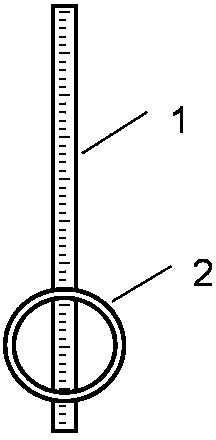
[0012] Such as figure 1 As shown, rigid body A 1 is a straight rod with uniform mass, made of magnetic material that can be attracted by a magnet; rigid body B 2 is a magnetic ring with uniform mass distribution, which is movably adsorbed on the straight rod. Move up and down along the straight rod, and the center of the ring is on the straight rod.
[0013] Such as figure 2 As shown, rigid body A 1 is a straight rod with uniform mass, made of magnetic material that can be attracted by a magnet; rigid body B 2 is a magnetic disk with uniform mass distribution, and the disk is movably adsorbed on the straight rod. Move up and down along the straight rod, the center of the disc is located on the straight rod.
PUM
 Abstract
Description
Claims
Application Information
 - R&D Engineer
- R&D Manager
- IP Professional
- Industry Leading Data Capabilities
- Powerful AI technology
- Patent DNA Extraction
Browse by: Latest US Patents, China's latest patents, Technical Efficacy Thesaurus, Application Domain, Technology Topic, Popular Technical Reports.
© 2024 PatSnap. All rights reserved.Legal|Privacy policy|Modern Slavery Act Transparency Statement|Sitemap|About US| Contact US: help@patsnap.com