A high-efficiency motor vehicle power generation system

A technology for power generation systems and motor vehicles, which is applied in electric braking systems, electric vehicles, machines/engines, etc. It can solve the problems of unable to meet the power requirements of automobiles, simple structure, and impracticality, so as to improve the shock absorbing effect and set up reasonably , the effect is obvious

Active Publication Date: 2016-11-30
吕英
View PDF6 Cites 0 Cited by
  • Summary
  • Abstract
  • Description
  • Claims
  • Application Information

AI Technical Summary

Problems solved by technology

[0005] The purpose of the present invention is to provide a high-efficiency motor vehicle power generation system, aiming to solve the technical problems that the traditional power generation device used for driving the car is simple in structure, impractical and unable to meet the power demand of the car

Method used


Image

  • A high-efficiency motor vehicle power generation system
  • A high-efficiency motor vehicle power generation system
  • A high-efficiency motor vehicle power generation system

Examples


Embodiment 1

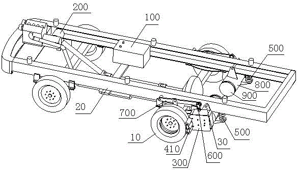
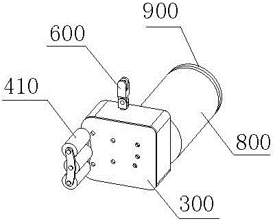
[0025] This embodiment discloses a high-efficiency motor vehicle power generation system, such as figure 1 As shown, it includes a battery 100 , a drive motor 200 connected to the battery 100 and providing power for the motor vehicle, a first generator, a transmission gearbox 300 and a power structure. In this example, see figure 2 , the power structure is a power generating wheel 410, the power generating wheel 410 is arranged close to the wheel 10 of the motor vehicle, and a first gear set connected to the power generating wheel 410 is arranged inside the transmission gearbox 300, and the first gear set is connected through a single-phase bearing The power shaft of the first generator, the first generator is electrically connected to the battery 100: the power generating wheel 410 is driven to rotate by the vehicle wheel 10, and the first generator is driven to rotate through the first gear set. The power shaft of the first generator is connected with an inertial flywheel ...

Embodiment 2

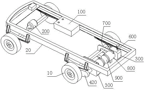
[0040] The structure of the high-efficiency motor vehicle power generation system disclosed in this embodiment is basically the same as that in Embodiment 1. The difference is that the power structure in this embodiment is a transmission chain (the transmission chain is installed inside the chain protection cover 420), and the transmission chains are respectively connected. Motor vehicle axle and first gear set. At the same time, the gear box 300 is arranged inside the vehicle frame 20 .

[0041] This high-efficiency motor vehicle power generation system in this embodiment is suitable for bridge vehicles.

[0042] In practical applications, the first generator, the second generator and the metamorphic wave box can also be integrated to further reduce the structure of the power generation system. This power generation structure is suitable for installation on motorcycles.

[0043] The effect that the high-efficiency motor vehicle power generation system in this embodiment is u...


PUM


Abstract

The invention discloses a high-efficiency motor vehicle power generation system, which comprises a storage battery, a driving motor connected to the storage battery, a first generator, a transmission gearbox and a power structure; The first gear set connected to the power structure, the first gear set is connected to the power shaft of the first generator through a single-phase bearing, and the first generator is electrically connected to the battery; the power structure is driven to rotate by the wheel or axle of the motor vehicle, and the first gear set It drives the first generator to rotate; it also includes a control circuit for controlling whether the first generator is working to generate electricity and an infrared balancer for detecting whether the car is in a downhill state. The control circuit is connected to the brake system of the motor vehicle and the infrared balancer; the control circuit is also connected Motor vehicle dashboard. The high-efficiency motor vehicle power generation system of the present invention has reasonable settings and high power generation efficiency, and is especially suitable for vehicles such as bridge cars, passenger cars, vans, container trucks, and motorcycles.

Description

technical field [0001] The invention relates to the field of automobile power generation, in particular to a high-efficiency motor vehicle power generation system, which utilizes the mechanical energy and bump energy in the driving process of the automobile to generate electricity, and stores or converts the electric energy into the power of the automobile. Background technique [0002] When the car is running, the energy of the car is constantly changing, and some of the energy changes can be used for power generation. For example, when the car brakes, its kinetic energy changes, and when the car goes downhill, its gravitational potential energy changes. In these cases, With a reasonable power generation system, these changing energies can be converted into electrical energy to provide power for cars. [0003] For example, the invention patent with the application number of 200810186030.0 discloses a driving power generation device. By combining the generator with the wheel...

Claims


Application Information

Patent Timeline
Patent Type & Authority Patents(China)
IPC IPC(8): B60K25/10B60L7/10F03G3/00F03G3/08
Inventor 陈国济
Owner 吕英
Why Eureka
Try Eureka