
A fabric scouring and bleaching device

A fabric, scouring and bleaching technology, applied in the treatment of textile material containers, spraying/jetting textile materials, etc., can solve the problems of short circuit of liquid flow, affecting the uniformity of scouring and bleaching, etc.

Inactive Publication Date: 2015-11-25
JIANGSU MEIKAILONG TEXTILE
View PDF3 Cites 0 Cited by
  • Summary
  • Abstract
  • Description
  • Claims
  • Application Information

AI Technical Summary

Problems solved by technology

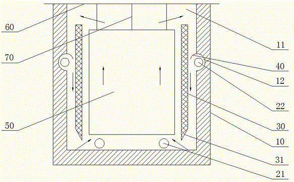
[0003] At present, the most widely used scouring and bleaching equipment is the scouring bucket. The common scouring bucket is a cuboid made of stainless steel plate, and there is a direct heating steam pipe at the bottom. The interlayer steam pipe is set in the interlayer. When the fabric is scouring and bleaching, the steam pipe at the bottom is closed, and only the interlayer steam pipe is used for heat preservation. Since the steam outlets of the interlayer steam pipe are all upward, when the steam is ejected, the training liquid is driven from the bottom into the interlayer. It overflows from the upper opening of the interlayer and flows to the center of the training barrel, forming a top-down flow direction. The top-down flow direction will cause the liquid flow to appear "short circuit", that is, the liquid flow does not pass through each fabric page, but It flows between pieces and closes the pages of the fabric, affecting the uniformity of scouring and bleaching

Method used


Image

  • A fabric scouring and bleaching device

Examples


Embodiment Construction

[0016] The present invention will now be further described in detail in conjunction with the accompanying drawings and embodiments. These drawings are all simplified schematic diagrams, only illustrating the basic structure of the present invention in a schematic manner, so it only shows the composition related to the present invention.

[0017] Such as figure 1 As shown, a fabric scouring and bleaching device comprises a cuboid-shaped barrel body 10 with one end being a fabric 50 inlet 11, the fabric 50 can be hoisted by a loop rope 70, the loop rope 70 is hung on the hanging rod 60, and the hanging rod 60 is left to rest. On the inlet 11 of the barrel 10 , the fabric 50 can be hung in the barrel 10 . The inner bottom of barrel body 10 of the present invention is provided with first steam pipe 21, directly heats first steam pipe 21, and steam is ejected upwards, makes practice liquid pour into the center of barrel body 10 first, makes practice liquid mix evenly; A baffle pla...


PUM


Abstract

The invention relates to a novel fabric scouring and bleaching device, which comprises a cuboid barrel body, wherein one end of the barrel body is provided with a fabric inlet, a first steam pipe is arranged at the bottom in the barrel body, a baffle plate which forms an interlayer together with the inner wall of the barrel body is arranged in the barrel body, a second steam pipe is arranged in the interlayer which is formed by the baffle plate and the inner wall of the barrel body, a circle of groove which is used for accommodating the second steam pipe and turning steam ejected from the second steam pipe to the bottom of the barrel body is arranged in the inner wall of the barrel body along the circumferential direction of the barrel body, and a flow-guiding plate which is used for enabling the steam to flow towards the bottom of the barrel body is arranged on the top edge of the groove. According to the fabric scouring and bleaching device disclosed by the invention, the steam ejecting direction of the second steam pipe is changed by arranging the groove in the inner wall of the barrel body and additionally installing the flow-guiding plate on the groove, so that the steam of the second steam pipe is ejected towards the bottom of the barrel body, the bottom-up circulating direction of a bleaching liquid is formed, and therefore the occurrence of a short-circuiting phenomenon is avoided; the bleaching liquid penetrates through pages of each fabric, so that the scouring and bleaching uniformity of the fabric is guaranteed.

Description

technical field [0001] The invention relates to a scouring and bleaching device, in particular to a fabric scouring and bleaching device. Background technique [0002] From the requirements of dyeing and finishing processing and clothing performance, the fabric should have good water absorption, soft feel and white appearance. The natural impurities contained, the size and colorant added in the weaving process, and various stains (such as oil stains, mud stains, rust stains) before dyeing and finishing processing, etc. Through scouring and bleaching processing, it is possible to directly obtain whitening products with luster, softness, pure whiteness, clear lines and good permeability, or provide suitable semi-finished products for dyeing and printing. [0003] At present, the most widely used scouring and bleaching equipment is the scouring bucket. The common scouring bucket is a cuboid made of stainless steel plate, and there is a direct heating steam pipe at the bottom. ...

Claims


Application Information

Patent Timeline
Patent Type & Authority Patents(China)
IPC IPC(8): D06B23/14D06B1/02
Inventor 秦健
Owner JIANGSU MEIKAILONG TEXTILE
Learn More