An automatic film sticking device on the surface of an optical drive

A film sticking device, optical drive technology, applied in packaging, labeling, transportation and packaging, etc., can solve the problems of low work efficiency, inaccurate manual filming on the surface of the optical drive, etc., to achieve high work efficiency, labor saving, and accurate filming effect.

Active Publication Date: 2016-05-25
苏州博智电子科技有限公司
View PDF6 Cites 0 Cited by
  • Summary
  • Abstract
  • Description
  • Claims
  • Application Information

AI Technical Summary

Problems solved by technology

[0004] The purpose of the present invention is to overcome the above-mentioned deficiencies in the prior art, based on solving the problem of inaccurate artificial film sticking on the surface of the optical drive and low work efficiency, a device for automatic film sticking on the surface of the optical drive is designed, which can automatically stick the film on the surface of the optical drive, and the position is accurate , and can also save a lot of manpower

Method used


Image

  • An automatic film sticking device on the surface of an optical drive
  • An automatic film sticking device on the surface of an optical drive
  • An automatic film sticking device on the surface of an optical drive

Examples


Embodiment Construction

[0018] The present invention will be described in detail below in conjunction with specific embodiments. The following examples will help those skilled in the art to further understand the present invention, but do not limit the present invention in any form. It should be noted that those skilled in the art can make several modifications and improvements without departing from the concept of the present invention. These all belong to the protection scope of the present invention.

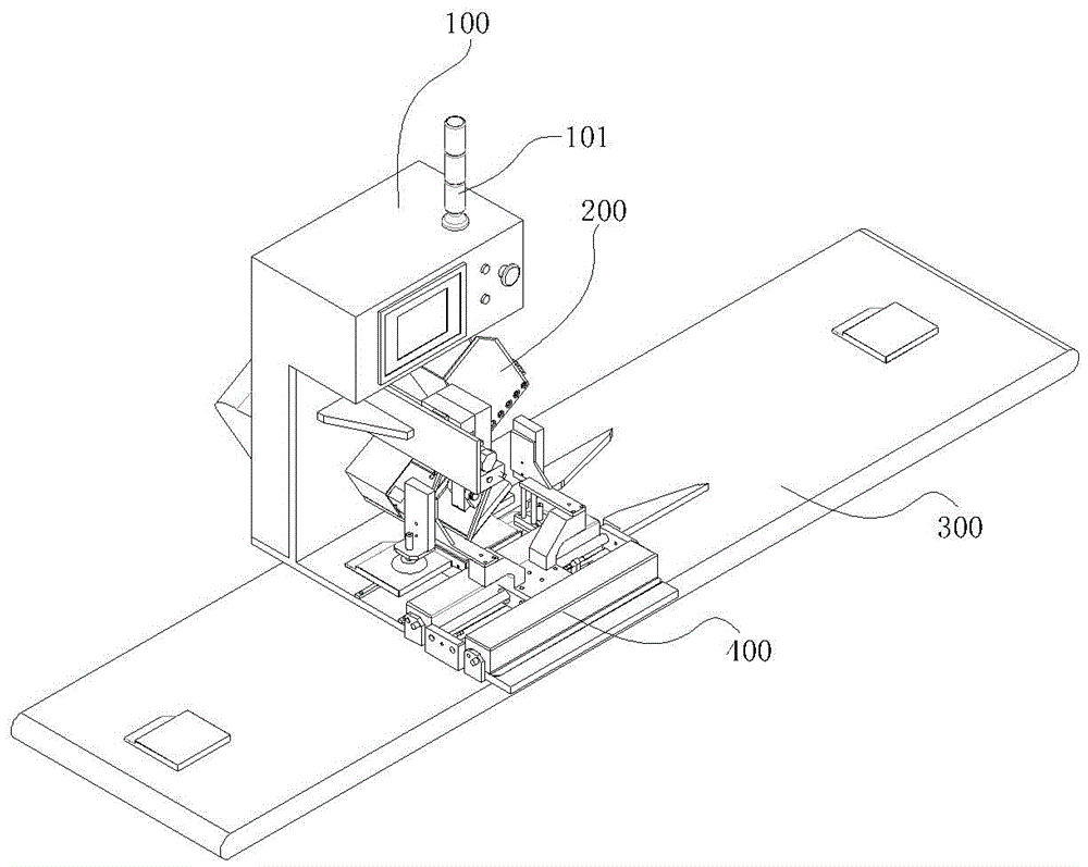
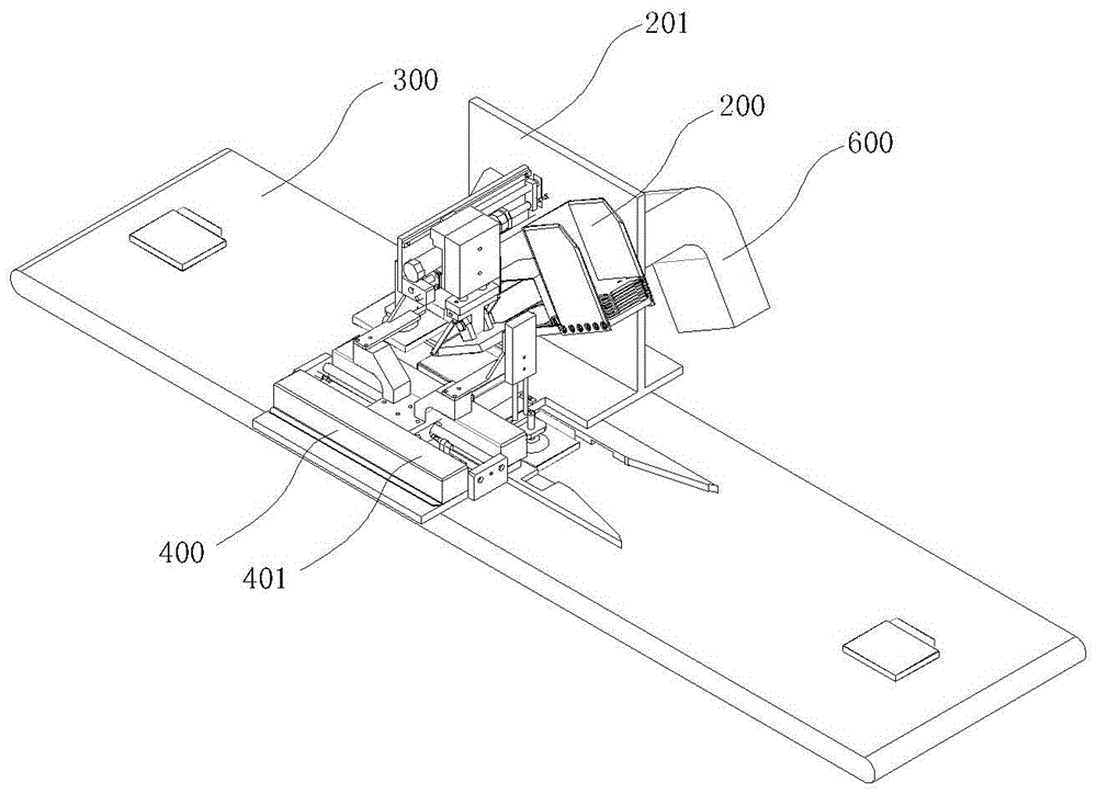
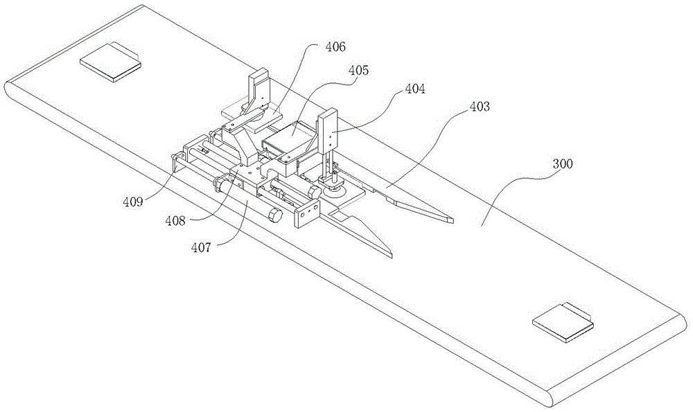
[0019] Please focus on figure 1 and figure 2 , an automatic film sticking device on the surface of an optical drive, including a console 100, and a warning light 101 is also arranged on the console 100, which can give an alarm in time when the device breaks down, and the console 100 is used to set and control the operation of the whole device; the suction film mechanism 200 , the bottom plate 300, the transmission mechanism 400 and the heat dissipation air duct 600, the transmission mechanism 40...


PUM


Abstract

The invention discloses an automatic film sticking device on the surface of an optical drive, which includes a console, a film suction mechanism, a bottom plate, a transmission mechanism and a cooling air duct. On the side of the mechanism; directly below the console, there is a film suction and pasting mechanism for absorbing film paper. The invention has the advantages of accurate film sticking, safety and reliability, and manpower saving, and has broad market prospects.

Description

technical field [0001] The invention relates to an automatic film sticking device on the surface of an optical drive, belonging to the technical field of computer electronic processing equipment. Background technique [0002] An optical drive is a machine used by a computer to read and write the contents of an optical disc, and it is also a relatively common component in desktop and notebook portable computers. As the application of multimedia becomes more and more extensive, the optical drive has become a standard configuration in many computer accessories. Optical drive can be divided into CD-ROM drive, DVD drive (DVD-ROM), Combo (COMBO), Blu-ray drive (BD-ROM) and recorder. [0003] In order to mark the manufacturer or express the model information on the CD-ROM, most of them use mold-printed codes or stick film paper with words to express the information required by the manufacturer. At present, the film sticking on the surface of the optical drive is done manually. Si...

Claims


Application Information

Patent Timeline
Patent Type & Authority Patents(China)
IPC IPC(8): B65C1/02
Inventor 喻建文叶莉莉陆源
Owner 苏州博智电子科技有限公司
Why Eureka
Try Eureka