Clamp for lower right mounting bracket assembly of IP body

A technology for installing brackets and IP bodies, applied in auxiliary devices, manufacturing tools, auxiliary welding equipment, etc., can solve the problems of inconvenient production and processing, low operation efficiency, inconvenient clamping and positioning, etc., to ensure the accuracy of clamping and positioning, structural design Reasonable and increase the effect of applicable surface

Active Publication Date: 2014-07-30
ANHUI DACHANG TECH
View PDF6 Cites 1 Cited by
  • Summary
  • Abstract
  • Description
  • Claims
  • Application Information

AI Technical Summary

Problems solved by technology

[0003] At present, the middle parts of the instrument panel beam used in the factory, especially the clamps of the lower right mounting bracket assembly of the IP body, are manually clamped, and the operating efficiency is relatively low. Quick clamping has not been realized, which affects the production efficiency of the instrument panel beam. Due to the special structure of the lower right mounting bracket assembly of the IP body, its two ends are bent, and the middle part is concave inward with a certain arc, which brings inconvenience to its clamping and positioning. The structural design of the bracket assembly fixture itself is unreasonable, and the IP body lower right mounting bracket assembly is not well positioned, which is prone to loosening and misalignment of the IP body lower right mounting bracket assembly, which will affect the processing accuracy and molding of the product The quality needs to be trimmed repeatedly after the inspection of the gage, which brings inconvenience to the production and processing

Method used


Image

  • Clamp for lower right mounting bracket assembly of IP body
  • Clamp for lower right mounting bracket assembly of IP body
  • Clamp for lower right mounting bracket assembly of IP body

Examples


Embodiment Construction

[0020] In order to make the technical means, creative features, goals and effects achieved by the present invention easy to understand, the present invention will be further elaborated below.

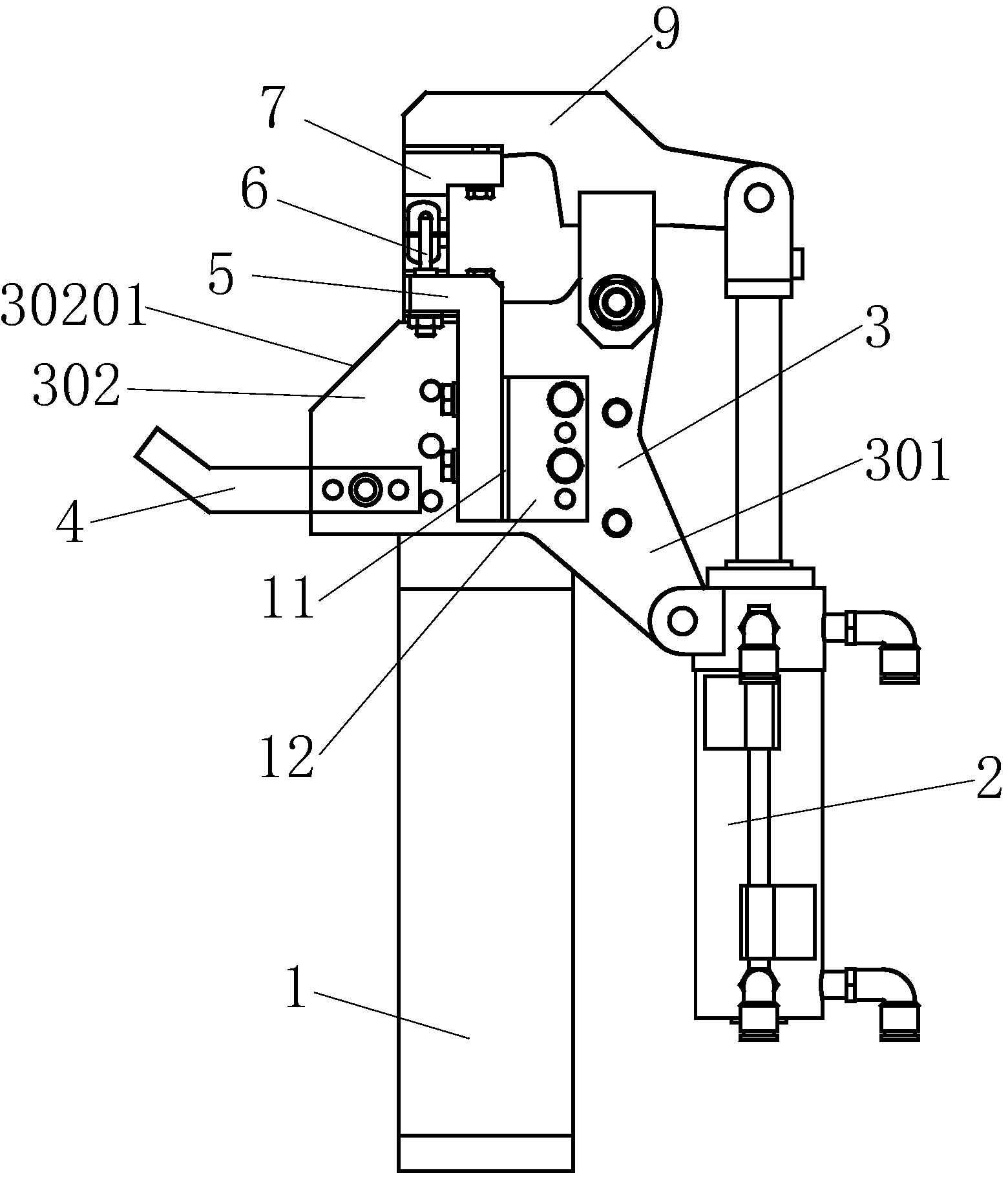
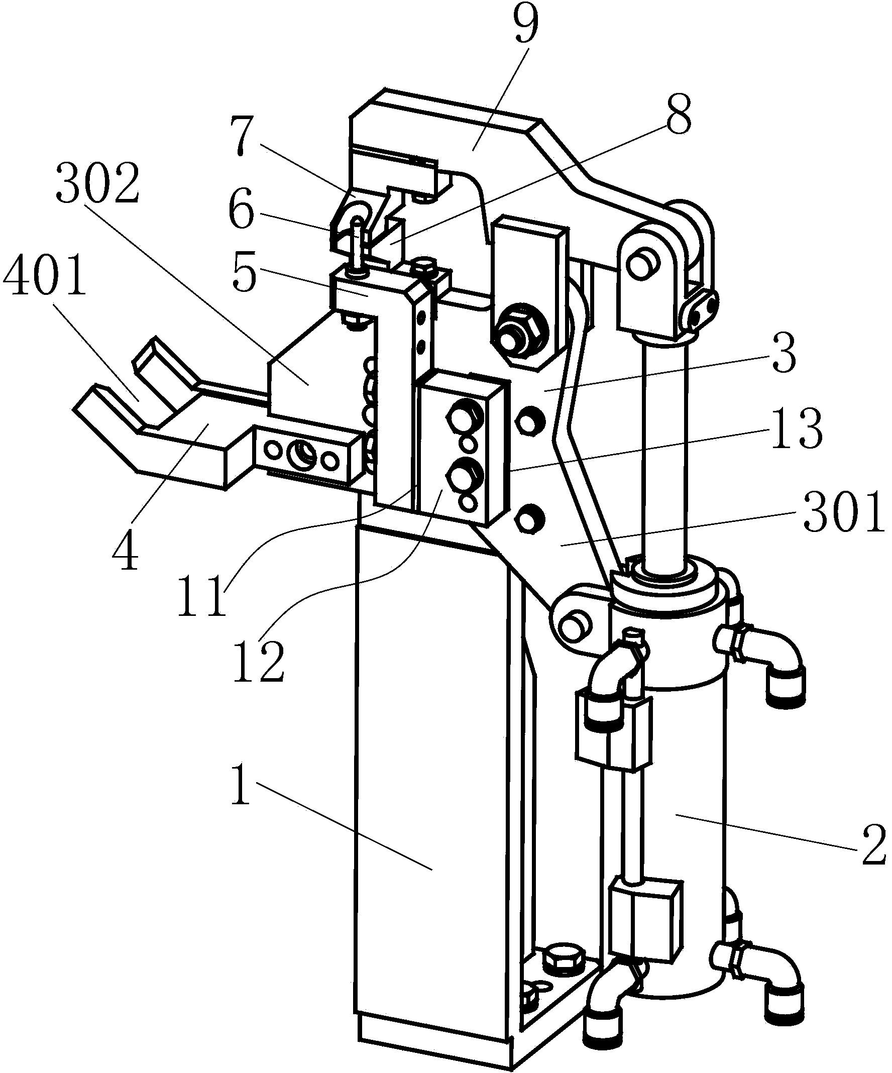
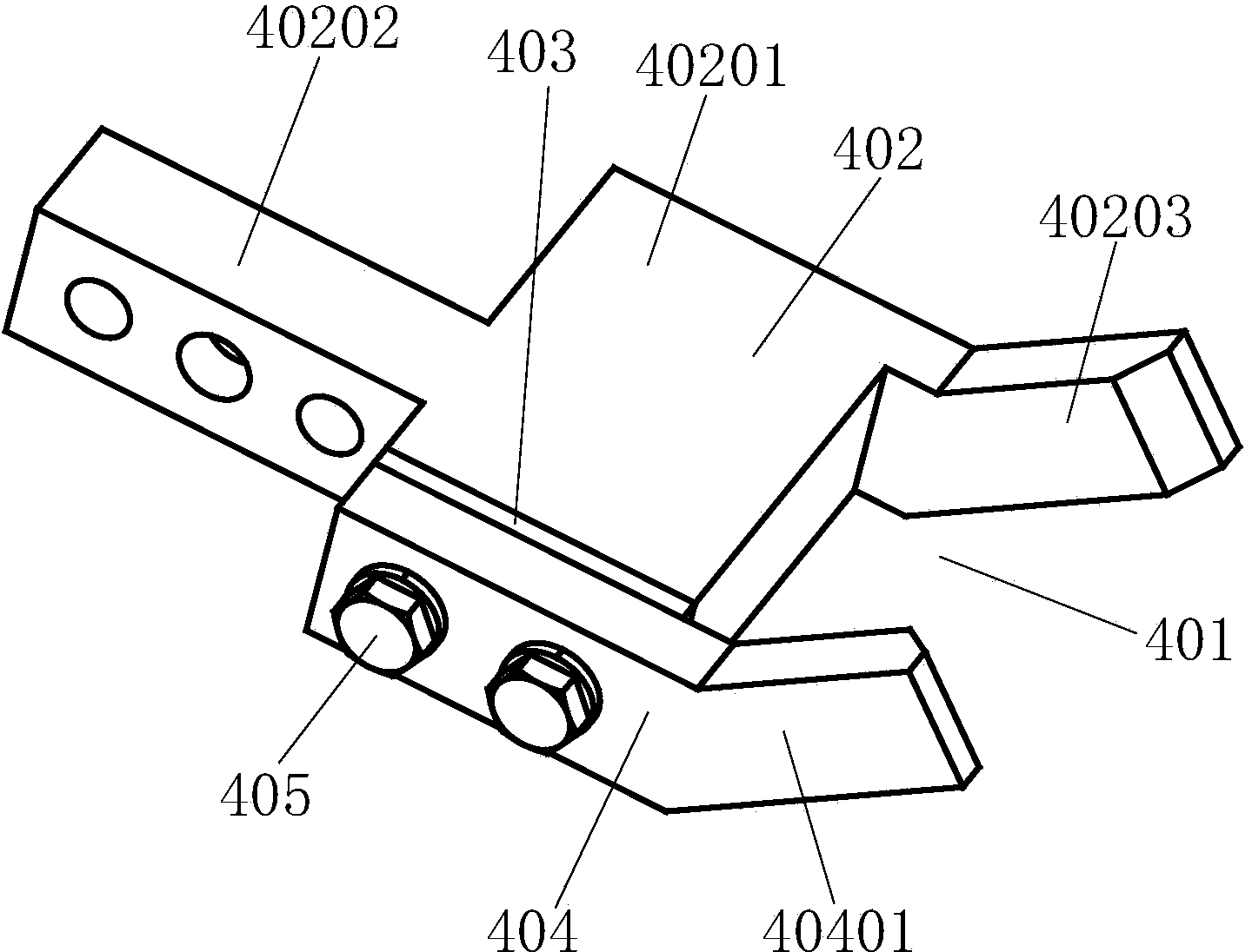
[0021] Such as Figure 1 to Figure 5 As shown, a jig for the lower right mounting bracket assembly of the IP body, including a stand 1, a connecting frame 3, a cylinder 2, a linkage pressure handle 9, a bias head 7, a bias seat 8, an L-shaped fixing frame 5, two free degree fixing hole distance adjustment device, positioning pin shaft 6 and U-shaped bracket 4, the connecting frame 3 is fixedly connected with the upper end of the stand 1, and the L-shaped fixing frame 5 is fixedly installed by a two-degree-of-freedom hole fixing distance adjustment device On the side of the middle part of the connecting frame 3, the lower right side of the connecting frame 3 is provided with a lower connection part 301, the middle part of the linkage pressing handle 9 is connected with the upper end of t...


PUM


Abstract

The invention relates to a clamp for a lower right mounting bracket assembly of an IP body. The clamp comprises a vertical base, a connecting frame, an air cylinder, a linkage pressing handle, a biasing head, a biasing base, an L-shaped fixed frame, a two-freedom-degree hole positioning distance adjusting device, a positioning hinge pin and a U-shaped bracket, wherein the connecting frame is fixedly connected with the upper end of the vertical base; the L-shaped fixed frame is fixedly mounted on the connecting frame through the two-freedom-degree hole positioning distance adjusting device; a lower connecting part is arranged at the lower right part of the connecting frame; the middle of the linkage pressing handle is connected with the upper end of the connecting frame; a left baffle is arranged on the left side of the connecting frame; the U-shaped bracket is fixedly connected with the lower part of the left baffle; the lower connecting part is connected with the air cylinder; one end of the linkage pressing handle is hinged to the air cylinder; the biasing head is mounted at the other end of the linkage pressing handle; the positioning hinge pin is connected with the upper end of the L-shaped fixed frame in an inserting manner; the biasing base is mounted at the side part of the L-shaped fixed frame. The clamp has the advantages of reasonable structural design, high automation degree, convenience for adjustment and control and the like, realizes automatic clamping and positioning instead of manpower, guarantees the clamping and positioning precision, has a fine adjustment function, and enlarges the application scope.

Description

technical field [0001] The invention relates to the technical field of auto parts processing, in particular to a jig for an IP body lower right mounting bracket assembly. Background technique [0002] As we all know, the automobile instrument panel beam assembly is the supporting framework of the automobile instrument system, and can also enhance the structural strength of the vehicle body. In the production and processing process of the automobile instrument panel beam, due to its relatively complex structure, welding is currently used for production. It is precisely because there are many parts on the instrument panel beam that it needs to be divided into different processes. Tailor welding, which also facilitates the clamping and positioning of the parts themselves, thus ensuring the processing accuracy of production and helping to improve the pass rate of parts. When dividing the process, the welding of sub-assemblies can be carried out first, such as the separate weldi...

Claims


Application Information

Patent Timeline
Patent Type & Authority Applications(China)
IPC IPC(8): B23K37/04
CPCB23K37/0435
Inventor 钱炳南胡伟王本玉
Owner ANHUI DACHANG TECH
Why Eureka
Try Eureka