
A method for controlling roll balance of a skin pass mill

A balance control and tempering machine technology, applied in the direction of rolling force/roll gap control, etc., can solve problems such as car jumping, unleveling, excessive roll gap deviation, etc., to reduce frequent adjustments, reduce roll gap deviation, Guarantee the effect of synchronous response

Inactive Publication Date: 2017-01-04
SHANGHAI BAOSTEEL IND TECHNOLOGICAL SERVICE
View PDF7 Cites 0 Cited by
  • Summary
  • Abstract
  • Description
  • Claims
  • Application Information

AI Technical Summary

Problems solved by technology

[0004] At the production site, due to the vibration of the hydraulic system, the deviation of the roll gap is often too large and the car jumps or cannot be leveled; or in the leveling and recoiling mode, the pressure output of the servo valve is pushed to oscillate, and the coil produces intermediate waves and waves during the rolling process. side waves

Method used


Image

  • A method for controlling roll balance of a skin pass mill
  • A method for controlling roll balance of a skin pass mill
  • A method for controlling roll balance of a skin pass mill

Examples


Embodiment Construction

[0021] The technical solutions provided by the present invention will be described in detail below in conjunction with specific examples. It should be understood that the following specific embodiments are only used to illustrate the present invention and are not intended to limit the scope of the present invention.

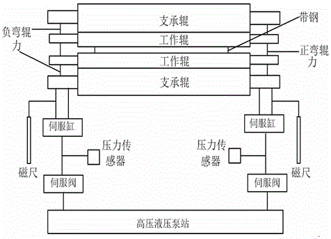
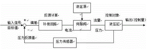
[0022] Such as figure 1 Shown is a structural schematic diagram of a skin pass mill, including hydraulic servo system control. The hydraulic servo system includes a high-pressure hydraulic pump station, two push-up servo hydraulic cylinders, two servo valves, a position sensor, a pressure sensor, and an accumulator Assembling and connecting pipe fittings, what adopted in the present embodiment of the position sensor are two magnetic rulers. The lower support roller is connected to the servo hydraulic cylinder, which drives its transmission. The servo hydraulic cylinder is respectively connected to the working side and the transmission side of the lower support ro...


PUM


Abstract

The invention discloses a roller balance control method of a planisher. Pressure given gains on two sides of a planishing working roller are changed to avoid the shock of a hydraulic system, so that the roller clearance deviation caused by the shock of the hydraulic system is avoided; meanwhile, as a dead zone control function is added in roller-system balance control, the frequent adjustment on the output of servo valves is reduced to realize roller-system dynamic balance.

Description

technical field [0001] The invention relates to a roller balance and synchronous control technology of a tempering mode of a tempering machine in the metallurgical industry, in particular to a balancing control method of a tempering machine. Background technique [0002] The leveling machine currently in use has a high degree of automation, and its hydraulic system adopts servo control. The hydraulic servo system of the tempering machine we use is composed of a high-pressure hydraulic pump station, two push-up servo hydraulic cylinders, two MOOG servo valves, position sensors, pressure sensors, accumulator groups, connecting pipes, etc. [0003] Its working principle is that the lower support roller of the tempering machine is pushed up by the upper cylinder and put in. Before the roller surface touches the coil, it adopts constant position control to ensure that the two ends are horizontally synchronized when going up. When the working rolls are in contact with the plate s...

Claims


Application Information

Patent Timeline
Patent Type & Authority Patents(China)
IPC IPC(8): B21B37/62
Inventor 吴洁旻华长浩
Owner SHANGHAI BAOSTEEL IND TECHNOLOGICAL SERVICE
Learn More