
Combined switchgear for voltage drop devices

A combination switch and voltage drop technology, which is applied in the setting of switchgear, panel/switch station circuit device, switchgear, etc., can solve the problems of reducing the insulation performance of the device, limited space in the box, and large space occupied by switchgear components. Achieve the effect of improving operation stability, improving anti-seismic function and ensuring test performance

Active Publication Date: 2016-06-15
江苏群菱能源科技有限公司 +1
View PDF5 Cites 0 Cited by
  • Summary
  • Abstract
  • Description
  • Claims
  • Application Information

AI Technical Summary

Problems solved by technology

[0004] Since the voltage drop device needs to be tested at different test sites when it is in use, the voltage drop device needs to be moved, and the device needs multiple switch cabinets with different functions to control the device, so multiple switch cabinets will cause Due to the bumpy transportation during the process, the switch cabinets are prone to displacement, which will cause damage to the busbar components connected between the switch cabinets. The harsh environment of wind farms and photovoltaic power stations is easy to corrode the voltage drop device, causing damage to the device, and even reducing the insulation performance of the device, causing safety problems
In addition, the voltage drop device is generally installed in a standard container. Due to the limited space in the box, multiple switchgear components take up a lot of space. In order to make the device compact, the small gaps between the various components are prone to collisions, resulting in short circuits, etc. question

Method used


Image

  • Combined switchgear for voltage drop devices
  • Combined switchgear for voltage drop devices

Examples


Embodiment Construction

[0016] Embodiments of the present invention will be described in detail below with reference to the accompanying drawings.

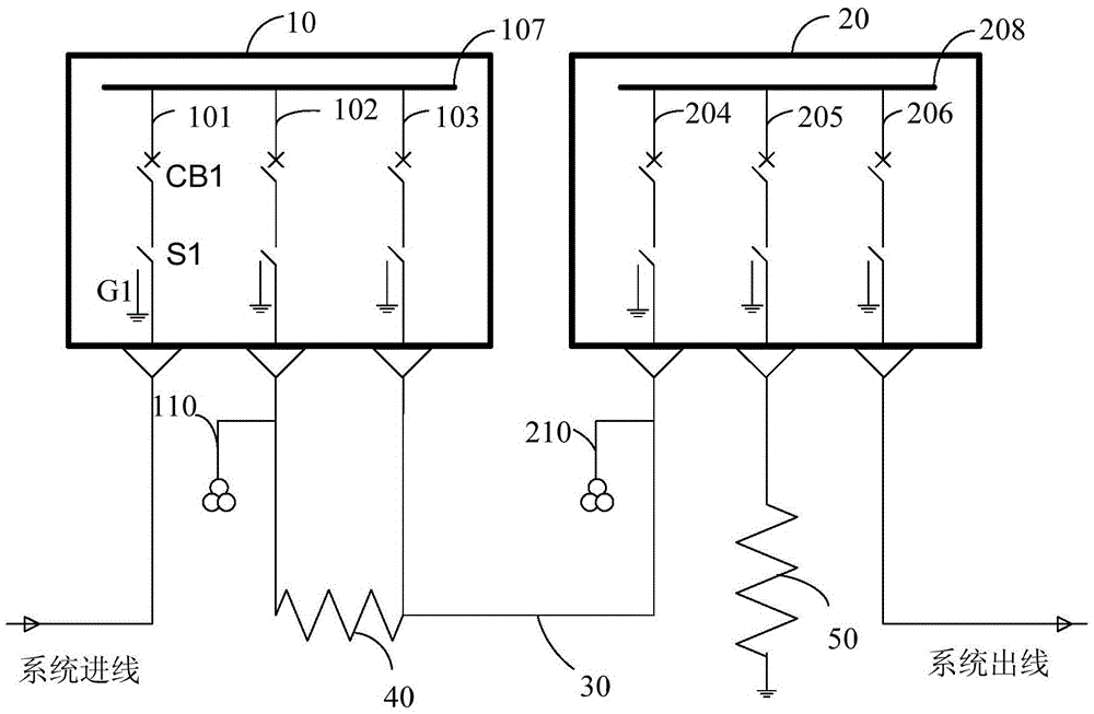
[0017] figure 2 A structural schematic diagram of a combined switchgear of the voltage drop device of the present invention is shown.

[0018] refer to figure 2 , the combined switchgear of the voltage drop device according to the embodiment of the present invention includes a first switchgear 10 and a second switchgear 20 . The first switch cabinet 10 includes a first switch unit 101 , a second switch unit 102 and a third switch unit 103 , and the second switch cabinet 20 includes a fourth switch unit 204 , a fifth switch unit 205 and a sixth switch unit 206 .

[0019] In this embodiment, all the switch units of the first switch cabinet 10 and the second switch cabinet 20 adopt the same structure, that is, each switch unit includes a circuit breaker, an isolation switch and a ground switch. For example, the first switch unit 101 includes a circuit ...


PUM


Abstract

The invention relates to a combination switch cabinet of a voltage drop device. The combination switch cabinet of the voltage drop device is characterized in that the combination switch cabinet comprises a first switch cabinet and a second switch cabinet, wherein the first switch cabinet comprises a plurality of switch units used for controlling a current limiting reactor, the second switch cabinet comprises a plurality of switch units used for controlling a short circuit reactor, and the first switch cabinet and the second switch cabinet are connected through a flexible cable. A gas tank sharing design that the switch units are sealed in a same gas tank is adopted for the combination switch cabinet, so that the fault of gas leakage caused by sealing failure among gas tanks when a plurality of single gas tank switches are connected is avoided; meanwhile insulativity among the units is increased, dustproof, dampproof and salt resistant functions are achieved, and the operation safety of the whole voltage drop device is improved.

Description

technical field [0001] The invention relates to the field of new energy access and control, in particular to a combined switch cabinet of a voltage drop device. Background technique [0002] Since the "Eleventh Five-Year Plan", my country's new energy power generation industry has developed by leaps and bounds. The newly installed capacity of wind power has doubled year after year, and the output of solar cells has grown rapidly with an average annual growth rate of more than 100%. However, while my country's new energy is developing rapidly, it is also facing quality and safety issues brought about by the large-scale connection of new energy to the power grid. In order to ensure the stability of the power grid after large-scale access to wind power, photovoltaic power generation and other new energy power generation, it is necessary that the power generation units such as wind power and photovoltaic power generation can still not be separated from the power grid when the vo...

Claims


Application Information

Patent Timeline
Patent Type & Authority Patents(China)
IPC IPC(8): H02B1/24H02B13/035
Inventor 姚承勇
Owner 江苏群菱能源科技有限公司
Learn More