An Optical Wavefront Error Improvement System Based on Discrete Pupil Gating

A wavefront error and wavefront technology, which is applied in the field of optical wavefront error improvement system, can solve problems such as difficulty in obtaining, high cost, and complex wavefront corrector, and achieve cost reduction and cost reduction, high real-time performance, and easier product The effect obtained

Inactive Publication Date: 2016-08-24
NANJING INST OF ASTRONOMICAL OPTICS & TECH NAT ASTRONOMICAL OBSE
View PDF4 Cites 0 Cited by
  • Summary
  • Abstract
  • Description
  • Claims
  • Application Information

AI Technical Summary

Problems solved by technology

[0007] The problem to be solved by this program: to overcome the shortcomings of the existing wavefront corrector in adaptive optics that are too complicated, too expensive, and difficult to obtain, and propose an optical wavefront error improvement system for discrete gating of the pupil, through discrete selection The discrete gating of the wavefront pupil is achieved through the system. On the basis of keeping the spatial frequency as complete as possible, the statistical performance of the wavefront error is effectively improved, and the original wavefront error of the optical system is improved.

Method used


Image

  • An Optical Wavefront Error Improvement System Based on Discrete Pupil Gating
  • An Optical Wavefront Error Improvement System Based on Discrete Pupil Gating
  • An Optical Wavefront Error Improvement System Based on Discrete Pupil Gating

Examples


Embodiment 1

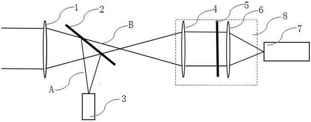
[0021] like figure 1 As shown, an optical wavefront error improvement system 10 based on pupil discrete gating is composed of an optical system main mirror 1, a beam splitter 2, a wavefront detector 3, a first lens 4, a shutter array 5, The second lens 6 and scientific imaging camera 7 are composed; the optical wavefront error improvement system is also provided with a computer (not shown in the figure), the wavefront detector 3 and the shutter array 5 are all connected to the computer, and the computer is used to detect The wavefront distortion information of the device 3 is used to control the shutter array 5 to gate the discrete wavefront of the pupil. The beam splitter 2 is installed between the main mirror 1 and the focal plane of the main mirror, and the shutter array 5 is installed at the exit pupil of the optical imaging system, between the first lens 4 and the second lens 6 . The first lens 4 , the shutter array 5 and the second lens 6 constitute a discrete gating sy...

Embodiment 2

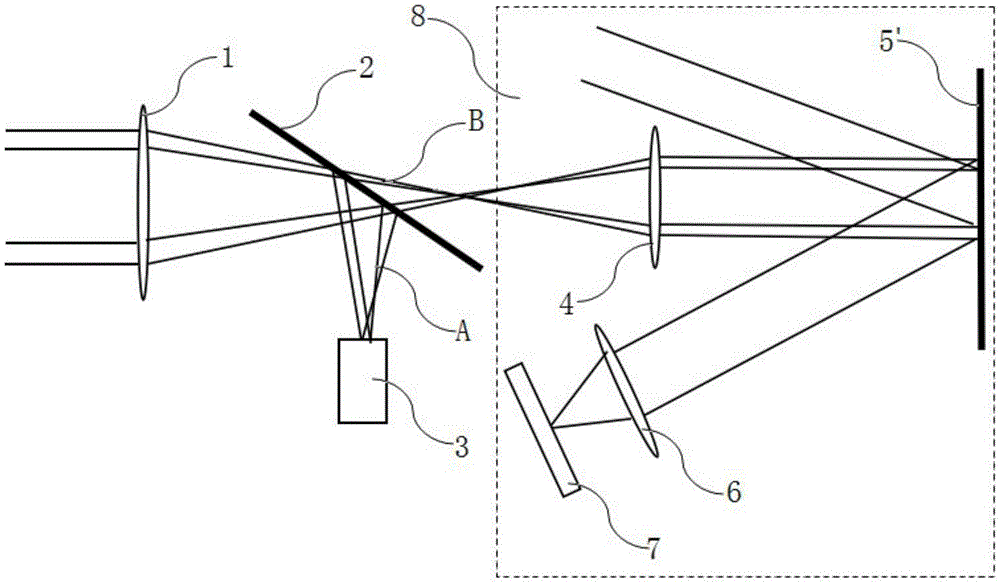
[0025] The composition of this embodiment is similar to that of Embodiment 1, except that the shutter array 5 in Embodiment 1 is replaced by a DMD system 5′. The first lens 4 , the DMD system 5′ and the second lens 6 constitute a discrete gating system 8 .

[0026] The conventional DMD system is developed by the Texas company of the United States, adopts the principle of microelectromechanical, and is a digital light modulator controlled by a binary digital signal. Its surface is distributed with closely arranged square microreflectors, and each microreflector can be flipped along its diagonal axis by ±12°, and the flipping frequency can reach several thousand hertz. When the deflection is +12°, the micro-mirror is in the on state, reflecting the light to the target optical system; when the deflection is -12°, the micro-mirror is in the off state, reflecting the light out of the optical system.

[0027] The system consists of an optical system main mirror 1, a beam splitter 2...


PUM


Abstract

An optical wavefront error improvement system based on pupil discrete gating is composed of an optical system main lens, a beam splitter, a wavefront detector, a discrete gating system and a scientific imaging camera, and further comprises a computer. The wavefront detector and the discrete gating system are connected through the computer. The computer is used for controlling the discrete gating system according to wavefront distortion information from the wavefront detector to carry out pupil discrete wavefront gating. Light entering the main lens is splitted into the two parts through the beam splitter; one part of light passes through the wavefront detector and serves as detection wavefront, and a wavefront signal is input to the computer and fed back to the discrete gating system; the other part of light directly enters the discrete gating system, the discrete gating system is used for controlling according to the wavefront signal and the control logic and carrying out the pupil discrete wavefront gating, and finally scientific images are obtained. The pupil discrete wavefront gating is achieved through the discrete gating system, and on the basis of keeping completeness of space frequency, the statistical performance of wavefront errors is improved.

Description

technical field [0001] The invention relates to an optical wavefront error improvement system based on pupil discrete gating, which belongs to the field of high-performance imaging such as active optics and adaptive optics, in particular to an optical wavefront error improvement system controlled by a discrete gating system . Background technique [0002] With the emergence and development of lasers, microelectronics and computers, the function and quality of optical instruments have been significantly developed and improved. But such efforts were limited to improving the internal quality of the instrument. However, in actual astronomical observations, it will be seriously affected by gravity deformation, thermal deformation, and even atmospheric turbulence. Maximizing the spatial resolution of ground-based astronomical optical systems to better observe the shape and structural details of celestial bodies is the dream of astronomers and the goal pursued by astronomical ins...

Claims


Application Information

Patent Timeline
Patent Type & Authority Patents(China)
IPC IPC(8): G02B26/00
Inventor 张勇王启蒙李烨平
Owner NANJING INST OF ASTRONOMICAL OPTICS & TECH NAT ASTRONOMICAL OBSE
Why Eureka
Try Eureka