Clamp device for friction experiment of drum type friction plate

A technology of clamping device and friction plate, which is applied in the field of brake friction, can solve the problems of not being able to meet the test requirements and shortages, and achieve the effect of simple and reliable structure, convenient disassembly and assembly, and easy popularization and application

Inactive Publication Date: 2014-07-23
SHANGHAI UNIV OF ENG SCI
View PDF5 Cites 5 Cited by
  • Summary
  • Abstract
  • Description
  • Claims
  • Application Information

AI Technical Summary

Problems solved by technology

At present, there is a lack of proprietary fixtures for the friction test of electric vehicle drum friction plates in the industry. There are very few clamping devices on the general friction testing machine, and they cannot meet the test requirements.

Method used


Image

  • Clamp device for friction experiment of drum type friction plate
  • Clamp device for friction experiment of drum type friction plate
  • Clamp device for friction experiment of drum type friction plate

Examples


Embodiment Construction

[0026] The present invention will be further described below in conjunction with accompanying drawing.

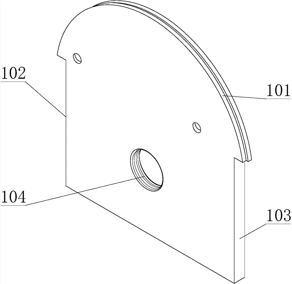
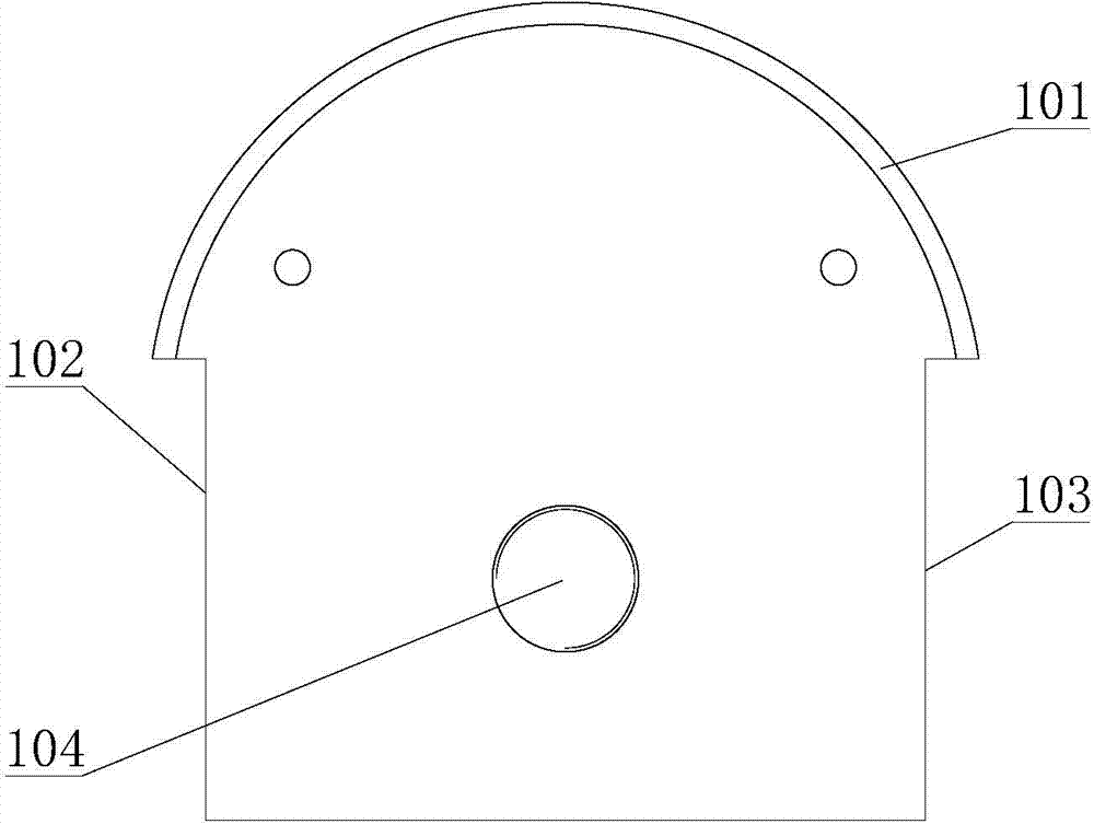
[0027] Such as Figure 1~2 As shown, the horizontally arranged vertical splint 1 is a special-shaped flat plate, and its upper edge 101 is a section of arc-shaped step surface protruding upwards. The left and right ends of the upper edge 101 and the left and right vertical edges 102 of the splint 1, 103 are connected, and the two vertical edges 102 and 103 are located inside the two ends of the upper edge 101 . The top half of the splint 1 is symmetrically provided with two through holes, and the bottom half is provided with threaded mounting through holes 104 .

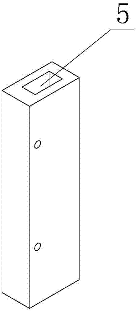
[0028] Such as image 3 , 6 As shown in and 7, a positioning groove 5 is provided at the upper end of the vertical clamping bar 3, and an elastic resisting element 6 protruding toward the notch is loaded into the positioning groove 5. The elastic resisting element 6 in the figure is a coil.

[0029] Such as ...


PUM


Abstract

The invention discloses a clamp device for a friction experiment of a drum type friction plate. A transversely arranged vertical clamp plate is an irregular flat plate; a section of arc-shaped stair surface which protrudes upwards is arranged on the upper edge of each vertical clamp plate; the left and right end parts of each upper edge are connected with two left and right vertical edges of the corresponding clamp plate; each two vertical edges are positioned on the inner sides of the two end parts of the corresponding upper edge; the stair surfaces of the upper edges of the two clamp plates are kept opposite and parallel to each other; the two clamp plates are integrally locked; the two upper edges define an arc-shaped clamping groove; two left and right opening ends of the clamping grooves are exposed out of the outer sides of two side edges, respectively; a vertical clamp strip is configured close to each of the two side edges below two ends of the clamp groove; positioning grooves are formed in two upper end parts of the two clamp strips towards two ends of the clamp groove; each positioning groove is internally provided with an elastic propping element which stretches out to the opening of the groove. The clamp device can sufficiently clamp the drum type friction plate according to experiment requirements, and is applicable to friction plates with different thicknesses, so that multiple purposes of one clamp are achieved; the device is good in connection with a universal friction experiment machine and convenient to assemble and disassemble, and the experiment can be accomplished by the device and the universal experiment machine.

Description

technical field [0001] The invention relates to the field of braking friction of an electric vehicle, in particular to a clamping device for a friction test of a drum-shaped friction plate. Background technique [0002] At present, the braking friction linings of electric vehicles generally use drum-shaped friction linings, and their friction performance directly affects the braking performance of electric vehicles. [0003] The drum-shaped friction plate is in the shape of an arc-shaped strip. When performing a friction test on it, it needs to be fully clamped along its arc-shaped outer edge, and then use the friction plate to rub the top of its arc-shaped outer edge back and forth, so as to measure the coefficient of static friction and dynamic friction. Coefficient and wear performance. At present, there is a lack of proprietary fixtures for the friction test of electric vehicle drum friction plates in the industry. There are very few clamping devices on the general fric...

Claims


Application Information

Patent Timeline
Patent Type & Authority Applications(China)
IPC IPC(8): G01N19/02G01N3/04
Inventor 张向伟金晓怡徐杨钮冬科封高歌周正珠周强周晓磊
Owner SHANGHAI UNIV OF ENG SCI
Why Eureka
Try Eureka