A method of wearing and installing flexible furnace rolls of continuous annealing furnace

A continuous annealing furnace, annealing furnace technology, applied in the direction of furnaces, heat treatment furnaces, furnace types, etc., can solve the problems of unsafety, low installation efficiency, high labor intensity, etc., and achieve the effect of eliminating damage

Active Publication Date: 2015-10-14
ANGANG CONSTR CONSORTIUM
View PDF9 Cites 0 Cited by
  • Summary
  • Abstract
  • Description
  • Claims
  • Application Information

AI Technical Summary

Problems solved by technology

[0002] At present, in the installation process of modern large-scale vertical continuous annealing furnace furnace rollers, the rigid furnace rollers and flexible furnace rollers are worn from the outside of the furnace shell to the furnace. The number of furnace rollers is large, and the rigid furnace rollers are directly worn Roller trolley, one-time assembly; for flexible furnace rollers, because the furnace rollers are slender, the slenderness ratio is often greater than 10, which is easy to vibrate and bend, and is usually worn from the outside of the furnace to the furnace by a roller trolley, and there are operations in the furnace. The personnel manually support the furnace roll and guide the roll mouth, and cooperate with the personnel outside the furnace to complete the furnace roll installation process. During the entire installation process, the furnace operator sometimes has to stand on the scaffold built in the furnace, which is labor-intensive and difficult. Very unsafe, installation efficiency is very low

Method used


Image

  • A method of wearing and installing flexible furnace rolls of continuous annealing furnace
  • A method of wearing and installing flexible furnace rolls of continuous annealing furnace
  • A method of wearing and installing flexible furnace rolls of continuous annealing furnace

Examples


Embodiment Construction

[0023] The specific embodiment of the present invention will be further described below in conjunction with accompanying drawing:

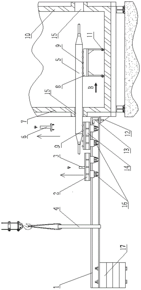
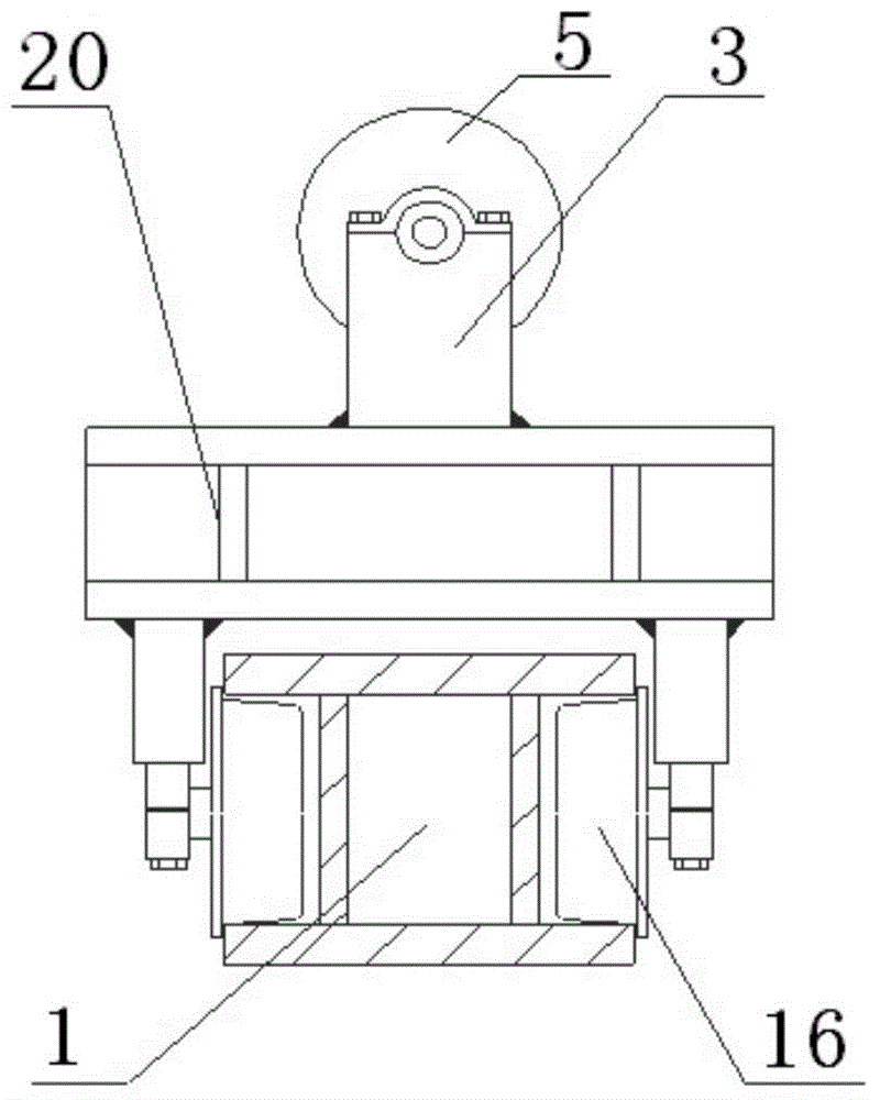
[0024] See figure 1 , figure 2 , is a schematic diagram of the process of wearing a flexible furnace roll in a continuous annealing furnace according to the present invention, mainly using a rolling trolley and a support and guide device to implement the wearing process of the flexible furnace roll, and the specific implementation steps are as follows:

[0025] 1. Preparation for hoisting of roller trolley

[0026] (1) Assemble the jig trailer 2 and the roller trailer 14 with the roller piercing trolley 1 respectively, and debug the safe and stable movement of the fixture trailer 2 and the roller trolley 14 on the roller piercing trolley; install the roller piercing trolley counterweight 17 at the roll piercing preparation position;

[0027] (2) Place the fixture trailer 2 on the left side of the hoisting point 4 of the lifting frame of the rol...


PUM


Abstract

The invention relates to the field of the installation of the large-scale continuous annealing furnaces and in particular relates to a penetrating method of a flexible furnace roller of a continuous annealing furnace. The penetrating method of the flexible furnace roller of the continuous annealing furnace is characterized in that the penetrating process of the flexible furnace roller is realized in such a manner that a roller penetrating trolley outside the annealing furnace cooperates with a supporting guide device in the annealing furnace. The penetrating method comprises the following specific implementation steps: 1) hoisting the flexible furnace roller to a roller trailer on the roller penetrating trolley; 2) hoisting the roller penetrating trolley to an installation position; 3) temporarily fixing the front end of the penetrating trolley with a furnace roller positioning iron angle; 4) suspending the front end of the flexible furnace roller in midair; 5) manually pushing the front end of the flexible furnace roller to penetrate into the annealing furnace; 6) moving the front end of the flexible furnace onto the supporting guide device in the middle part in the furnace; 7) fixing the front end of the flexible furnace after the e front end of the flexible furnace penetrates into a furnace shell roller mouth bearing box at the working side; 8) removing a positioning pin and returning the roller penetrating trolley to a roller penetrating preparation position. Compared with the prior art, the penetrating method of the flexible furnace roller of the continuous annealing furnace has the beneficial effects that accurate and quick roller mouth aligning penetration is realized and the damage of the surface of the flexible furnace roller is avoided.

Description

technical field [0001] The invention relates to the field of installation of large continuous annealing furnaces, in particular to a method for installing flexible furnace rollers of the continuous annealing furnace. Background technique [0002] At present, in the installation process of modern large-scale vertical continuous annealing furnace furnace rollers, the rigid furnace rollers and flexible furnace rollers are worn from the outside of the furnace shell to the furnace. The number of furnace rollers is large, and the rigid furnace rollers are directly worn Roller trolley, one-time assembly; for flexible furnace rollers, because the furnace rollers are slender, the slenderness ratio is often greater than 10, which is easy to vibrate and bend, and is usually worn from the outside of the furnace to the furnace by a roller trolley, and there are operations in the furnace. The personnel manually support the furnace roll and guide the roll mouth, and cooperate with the pers...

Claims


Application Information

Patent Timeline
Patent Type & Authority Patents(China)
IPC IPC(8): C21D9/54
Inventor 姜长平傅海
Owner ANGANG CONSTR CONSORTIUM
Why Eureka
Try Eureka