
CNC milling machine

A CNC milling machine and milling machine technology, applied in the field of milling machines, can solve the problems of shortened life, small worktable area, easy to drop, etc., and achieve the effects of increasing frictional resistance, increasing contact area, and reducing labor intensity

Inactive Publication Date: 2014-07-23
FOSHAN FENGBAO PRECISION MACHINE
View PDF6 Cites 9 Cited by
  • Summary
  • Abstract
  • Description
  • Claims
  • Application Information

AI Technical Summary

Problems solved by technology

However, there are still many problems in the current CNC machine tools: 1. The workbench area of ​​the milling machine is small, which is used as a positioning support for the processed parts, and there is no space for storing the parts to be processed or the finished products. The cylindrical workpiece placed on the workbench It is particularly easy to fall, and it may damage the workpiece in the slightest, or injure the nearby workers in severe cases. There are certain safety hazards; 2. The contact area between the workbench and the guide rail is small, and the anti-suspension effect is insufficient; 3. The lifting of the milling machine Because the table is in direct contact with the ground, it is easy to get wet and rust; 4. The liquid receiving tank under the workbench stores the used cutting fluid. Since the cutting fluid is mixed with a large amount of metal chips, the tank needs to be removed after processing. 5. The scale grating and grating reading head are directly exposed and installed on the machine tool, which is not only unsightly, but also the optical components are exposed in the production workshop environment for a long time, which greatly shortens the shorten its life, affect its detection accuracy, and directly reduce the quality of processed products

Method used


Image

  • CNC milling machine
  • CNC milling machine
  • CNC milling machine

Examples


Embodiment Construction

[0033] The specific embodiments of the present invention will be described in further detail below in conjunction with specific examples.

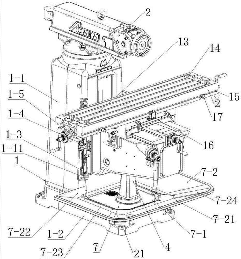
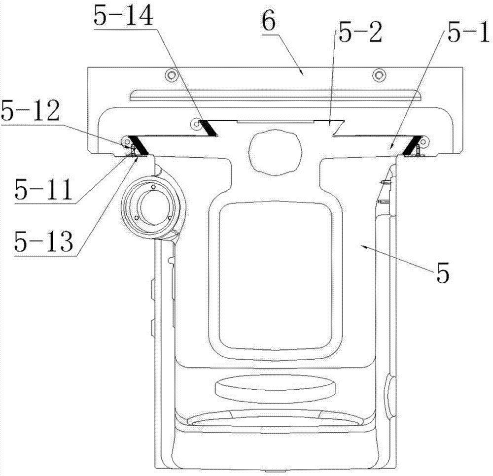
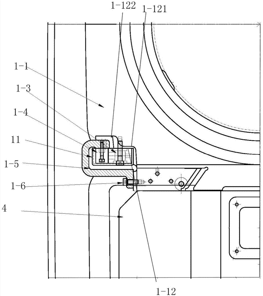
[0034] like Figure 1-Figure 7 As shown, a kind of numerical control milling machine of the present invention comprises numerical control device, bed 1 and the milling mechanism 2 that is arranged on it, workbench 3, infeed mechanism, lifting table 4 and cooling, lubricating system 22, bed 1 is controlled by lifting The pedestal 1-1 and the milling machine base 1-2 are formed, and the workbench 3 is movably arranged on the transverse feed mechanism through a guide rail seat 5 and a saddle 6 matched with the guide rail seat 5, and the transverse feed mechanism is arranged on the lifting table 4, The milling mechanism 2 is installed on the top of the lifting platform 1-1 through the rotary disc 6, the milling machine base 1-2 is provided with a liquid receiving tank 7, and the milling machine base 1-2 is provided with a liquid collecting cyl...


PUM


Abstract

The invention discloses a CNC milling machine. The CNC milling machine comprises a numerical control device, a machine body, a milling mechanism, a workbench, a transverse feeding mechanism, a lifting table and a cooling and lubricating system, wherein the milling mechanism, the workbench, the transverse feeding mechanism, the lifting table and the cooling and lubricating system are arranged on the machine body. The machine body is composed of a lifting table seat and a milling machine base. The milling mechanism is mounted on the top of the lifting table seat through a rotary disk. The milling machine base is provided with a liquid receiving groove. The CNC milling machine is characterized in that the milling machine base is provided with a liquid collection tank, a filtering device, a circulating pipeline and a circulating water pump, the liquid collection tank, the filtering device and the circulating pipeline are connected with the liquid receiving groove, and the circulating water pump is connected with the circulating pipeline; the lifting table seat is provided with a grating scale, a grating scale reading head and a reading head seat, the grating scale reading head is arranged on the reading head seat, the reading head seat is arranged on the lifting table, and the lifting table seat is provided with a recess for containing the grating scale; a guide rail seat is provided with a dovetail rail, and the dovetail rail is provided with a dovetail guide portion; a carrying table is arranged at the front end of the workbench, and a stop mechanism is arranged at the rear end of the workbench; the four corners of the lifting table seat are respectively provided with an L-shaped supporting leg. The CNC milling machine is simple in structure, convenient to use and high in production efficiency.

Description

technical field [0001] The invention relates to the technical field of milling machines, in particular to a numerically controlled milling machine. Background technique [0002] CNC milling machine is a machine tool that integrates a digital control system on an ordinary milling machine and can perform milling more accurately under the control of program codes. There are various forms of CNC milling machines. Although different types of CNC milling machines are different in composition, they have many similarities. The machine tool consists of 6 main parts, namely the bed part, the milling mechanism part, the worktable part, the transverse feed part, the lifting table part, the cooling and lubricating part. The internal layout of the bed is reasonable and has good rigidity. There are 4 adjusting bolts on the base to facilitate the horizontal adjustment of the machine tool. The cutting fluid storage tank is located inside the machine base. From the requirements of the devel...

Claims


Application Information

Patent Timeline
Patent Type & Authority Applications(China)
IPC IPC(8): B23Q1/26B23Q11/12B23Q11/00B23Q1/01B23Q17/24
CPCB23C1/02B23Q1/015B23Q1/017B23Q1/26B23Q11/10B23Q11/1069B23Q17/24
Inventor 陈易濬
Owner FOSHAN FENGBAO PRECISION MACHINE
Learn More