
A bending line mechanism

A technology of bending line and bending device, which is applied in assembly machines, lighting and heating equipment, sorting and other directions, can solve the problem of no bending pin pipelines, etc., achieve simple structure and function implementation, and reduce floor space. , the effect of improving the efficiency of production operations

Inactive Publication Date: 2015-12-02
AD TOYO LIGHTING GUANGZHOU
View PDF6 Cites 0 Cited by
  • Summary
  • Abstract
  • Description
  • Claims
  • Application Information

AI Technical Summary

Problems solved by technology

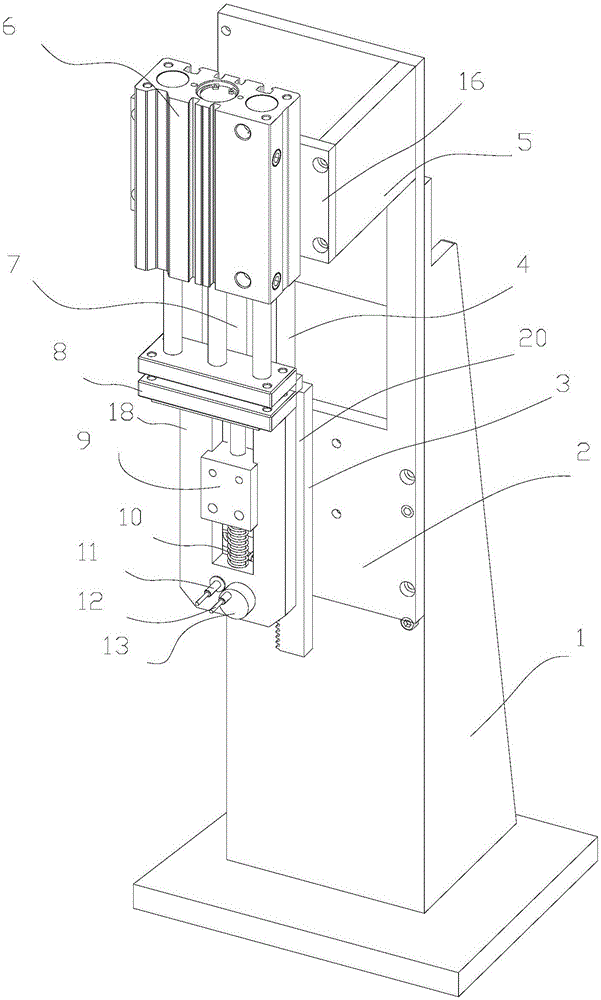
[0002] During production and processing, it is often necessary to bend the pins or other metal wires of some workpieces or components, especially when some grounding wires need to be connected to the shell; at present, there is no institutional device that can be easily bent Operation of folded pin pipeline

Method used


Image

  • A bending line mechanism
  • A bending line mechanism

Examples


Embodiment

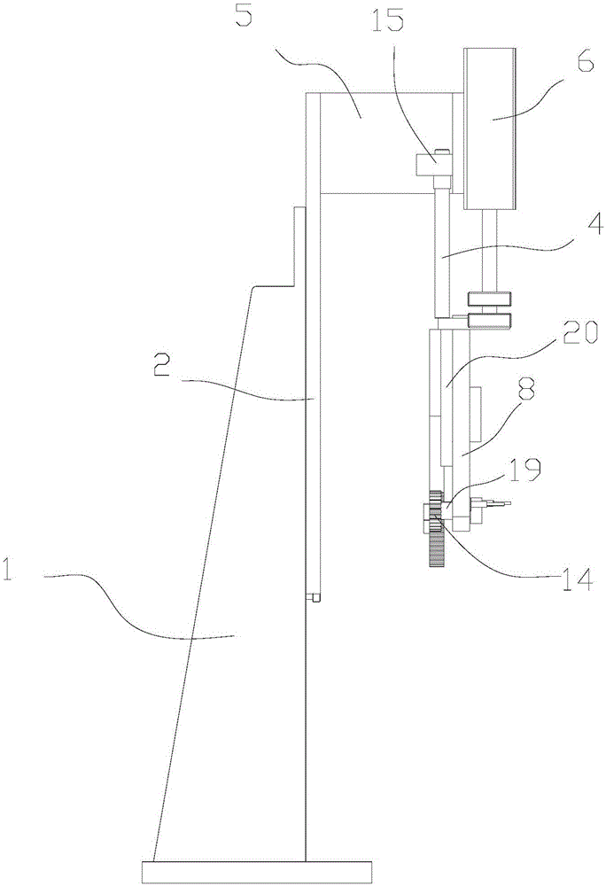
[0047] see figure 1 , is an embodiment of the bending line mechanism of the present invention, which includes: a support platform 1, a cantilever group (which includes: a fixed panel 2, an arm plate 5, and a mounting plate 16), a cylinder 6, an adjustment frame 15, a total pull rod 7, a bearing Plate 8, pressing down pull bar 4, lower pressing plate 18, connecting plate 20, guide rod 17, spring, slide block 9 and bending line device (it comprises: gear 14, rack 3, axle 13, axle sleeve 19, bending needle 11, threading needle 12), wherein:

[0048] The chassis of the support platform 1 is placed horizontally; it is used for fixing and installing the cantilever group.

[0049] The cantilever group includes: fixed panel 2, arm plate 5 and mounting plate 16; one end of the cantilever group is fixed on the support platform 1, and the other end is suspended in the air; specifically: the fixed panel 2 of the cantilever group is fixed on the support platform 1 with screws, and the arm...


PUM


Abstract

Disclosed is a smart production system of an LED lamp, the system comprising an automatic assembling mechanism (5), an automatic aging mechanism (4) connected to the automatic assembling mechanism (5), an automatic detecting device (2) connected to the automatic aging mechanism (4), an automatic packaging device (1) connected to the automatic detecting device (2), an automatic conveying device (3) connected to the automatic packaging device (1), and a master control unit which is connected to the automatic packaging mechanism (5), the automatic aging mechanism (4), the automatic detecting device (2), the automatic packaging device (1) and the automatic conveying device (3). The system successively, along a guide rail, comprises: a lamp body wiring device, a lamp holder installing device, an electrical board installing device, a wire management device, a wire bending and pressing device, a lamp holder and outer sleeve integrating device, an adhesive coating device, a light source board assembling device, a circuit welding device and a lampshade assembling device. Performing automated design on various processes greatly saves the cost of human resources and enhances the production efficiency.

Description

technical field [0001] The invention relates to the field of industrial production automation, in particular to a bending line mechanism. . Background technique [0002] During production and processing, it is often necessary to bend the pins or other metal wires of some workpieces or components, especially when some grounding wires need to be connected to the shell; at present, there is no institutional device that can be easily bent The operation of folding the pin pipeline. [0003] It is not difficult to see that there are certain defects in the prior art. Contents of the invention [0004] The technical problem to be solved by the present invention is to provide a bending wire mechanism, which is convenient for the operation of bending stitches, pipelines or similar metal wires, and has the characteristics of simple structure and realization of functions, complete functions and high degree of automation. [0005] A bending line mechanism, including: a support platf...

Claims


Application Information

Patent Timeline
Patent Type & Authority Patents(China)
IPC IPC(8): B21F1/00
CPCB07C5/34B23P21/004F21K9/90
Inventor 关崇安
Owner AD TOYO LIGHTING GUANGZHOU
Learn More