
Automobile generator rotor framework

A technology for automobile generators and rotor skeletons, applied to the rotating parts of the magnetic circuit, the shape/style/structure of the magnetic circuit, etc., can solve the problem that the insulating liquid cannot fully penetrate the copper wire, there is no fixing effect, and the generator does not generate electricity and other problems, to achieve the effect of avoiding copper wire breakage, eliminating no power generation, and preventing copper wire breakage

Inactive Publication Date: 2014-07-16
重庆博耐特实业(集团)有限公司
View PDF6 Cites 2 Cited by
  • Summary
  • Abstract
  • Description
  • Claims
  • Application Information

AI Technical Summary

Problems solved by technology

However, in this patent, the position of the paint-dipping hole is set on the inner side of the skeleton fan blade. After the rotor is assembled, the claw pole will cover the paint-dipping hole, so the insulating liquid cannot fully penetrate into the copper wire and fix the copper wire.
[0003] The existing rotor skeleton usually has protruding parts on the baffles at both ends, as shown in the skeleton disclosed in Chinese patent ZL201120306315.0 on August 22, 2011. The protruding parts are only used for the installation and alignment of the claw poles. There is no fixing effect. When the rotor rotates at high speed, the frame will shift due to inertia, causing the copper wires around the frame to break, and the generator will not generate electricity.

Method used


Image

  • Automobile generator rotor framework
  • Automobile generator rotor framework
  • Automobile generator rotor framework

Examples


Embodiment Construction

[0015] Below in conjunction with accompanying drawing and embodiment the present invention will be further described:

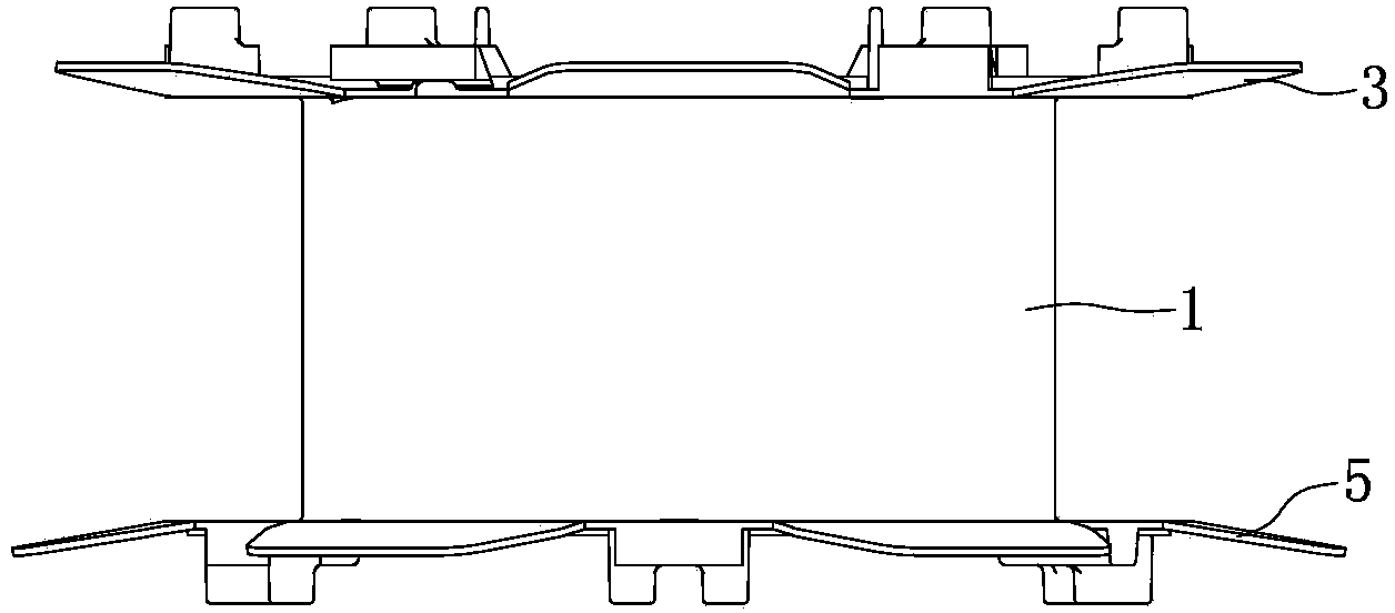
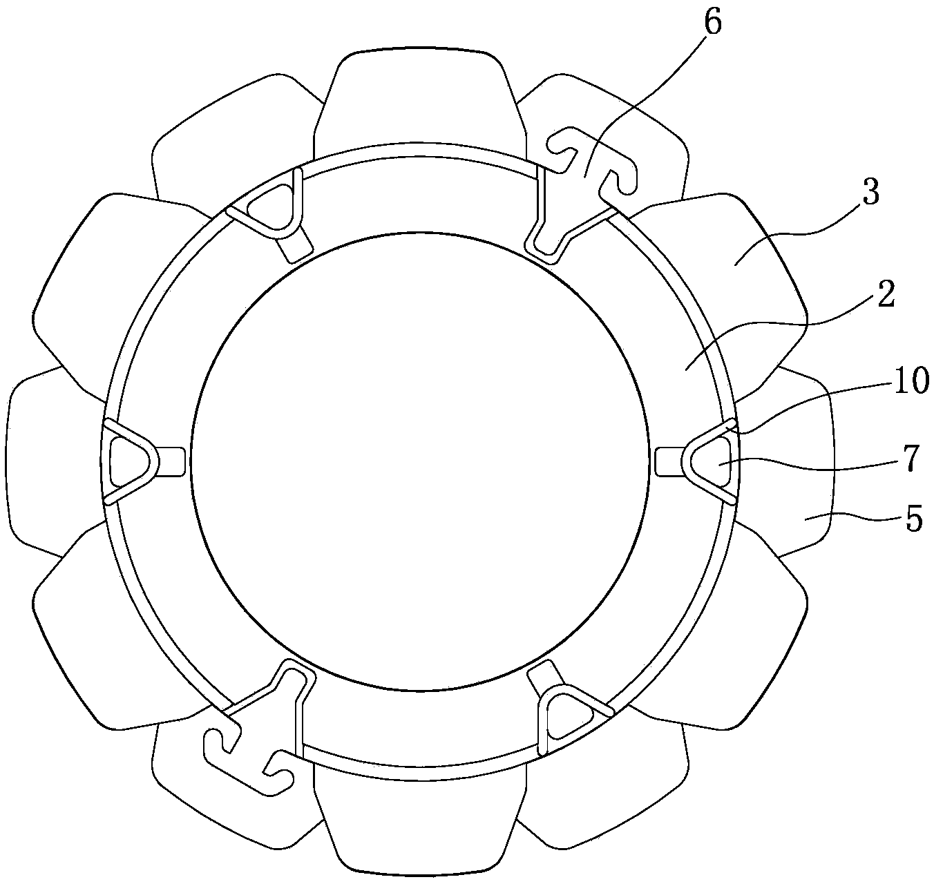
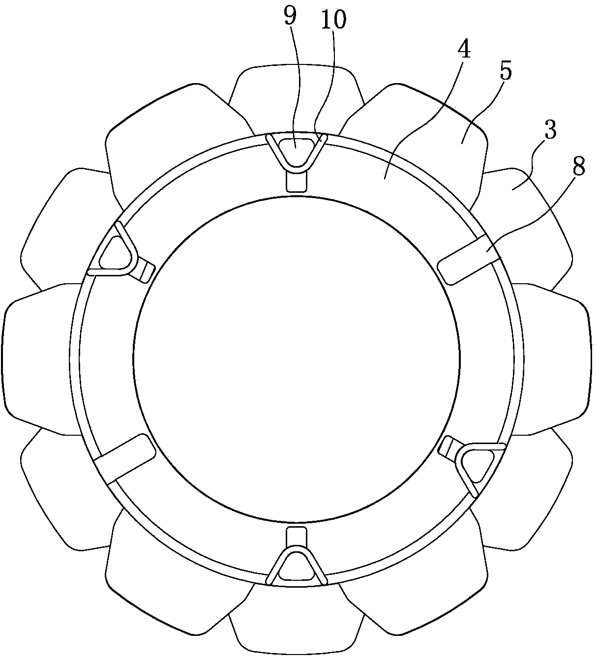
[0016] Such as figure 1 , figure 2 , image 3 and Figure 4 As shown, the cylinder body 1 is a short straight cylindrical structure with both ends open, and one end of the cylinder body 1 is integrally formed with a first baffle plate 2, and two winding parts 6 are integrally formed on the first baffle plate 2, and The periphery of the first baffle 2 is distributed with a plurality of first fan blades 3 uniformly distributed on the circumference, and the first fan blades 3 are integrated with the first baffle 2 . The other end of the barrel 1 is integrally formed with a second baffle plate 4, and a plurality of second fan blades 5 evenly distributed on the circumference are distributed on the periphery of the second baffle plate 4. The second fan blades 5 and the second baffle plate 4 are An integral structure, and the second fan blade 5 is misaligned wi...


PUM


Abstract

The invention discloses an automobile generator rotor framework. A first baffle (2) is arranged at one end of a barrel (1), a second baffle (4) is arranged at the other end of the barrel (1), two sets of first holes (7) are formed in the first baffle (2), and each first hole (7) is formed between two adjacent first fan blades (3). Two protruding edges (8) are arranged on the second baffle (4), the two protruding edges (8) are arranged on the same straight line, two sets of second holes (9) are formed in the second baffle (4) and are formed in the two sides of the center connecting line of the two protruding edges (8) respectively, and each second hole (9) is formed between two adjacent second fan blades (5). According to the automobile generator rotor framework, insulation liquid can be completely permeated into the innermost layer of a copper wire, a claw pole, the framework and the copper wire are completely fixed, meanwhile, the framework and the claw pole can be fixed in the circumferential direction, the framework is prevented from shifting or breaking away, and therefore the copper wire is effectively prevented from being broken, and the defect that a generator does not generate electricity is overcome.

Description

technical field [0001] The invention belongs to the technical field of automobile generators, and in particular relates to a skeleton of a rotor of an automobile generator. Background technique [0002] The rotor of an automobile generator is composed of claw poles, windings, skeletons, rotor shafts and collector rings. Applying insulating liquid on the rotor is used for rotor insulation and fixing the rotor skeleton and claw poles. However, the rotor generally winds the copper wire and installs the claw poles before applying the insulating liquid. Since there is no hole in the skeleton, when the insulating liquid is applied, only the surface of the copper wire contacts the insulating liquid, and the insulating liquid cannot penetrate into the copper wire. The copper wire inside the skeleton cannot be fixed. In this way, when the rotor rotates at high speed, the inner copper wire and the outer fixed part copper wire will break, causing the generator to fail to generate ele...

Claims


Application Information

Patent Timeline
Patent Type & Authority Applications(China)
IPC IPC(8): H02K1/28
Inventor 朴葵镐金暎道
Owner 重庆博耐特实业(集团)有限公司
Learn More