
A pulse tube refrigerator

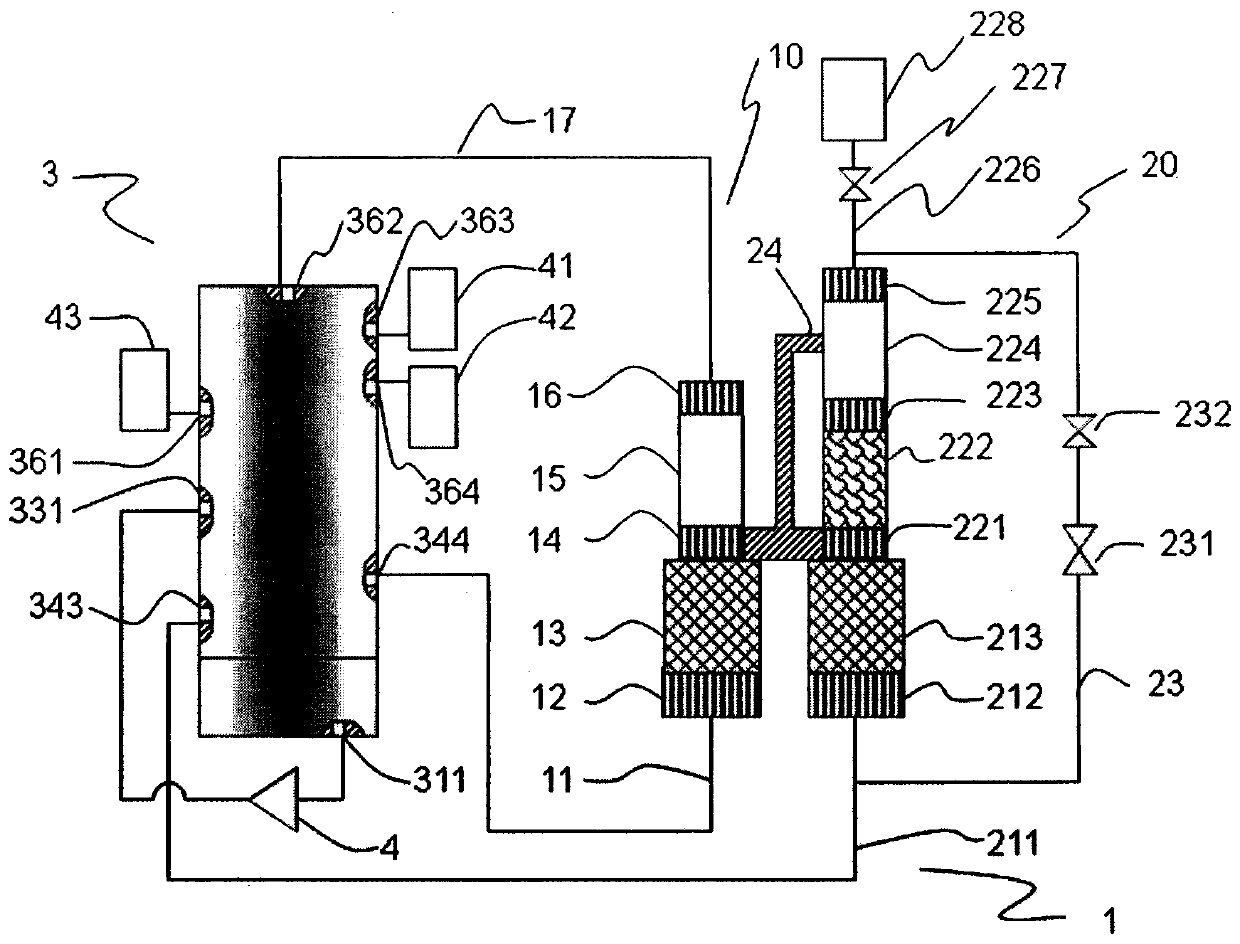
A technology for pulse tube refrigerators and compressors, which is applied in refrigerators, refrigeration and liquefaction, compressors, etc., can solve the problems that cannot be put into large-scale applications, achieve good contact, stable sealing performance, and reduce cost

Active Publication Date: 2019-05-03
朱绍伟
View PDF5 Cites 0 Cited by
  • Summary
  • Abstract
  • Description
  • Claims
  • Application Information

AI Technical Summary

Problems solved by technology

Therefore, multi-gas storage type pulse tube refrigerators have high efficiency, but cannot be put into large-scale applications

Method used


Image

  • A pulse tube refrigerator
  • A pulse tube refrigerator
  • A pulse tube refrigerator

Examples


Embodiment 2

[0033] In Embodiment 2, the first stator 34 and the second stator 36 tightly press the mover 35 together, and the service life is still limited. In order to achieve longer life, the rotor 35 can be supported by bearings, so that it maintains a small gap with the contact surfaces of the first stator 34 and the second stator 36 to obtain a gap seal with a small amount of leakage.

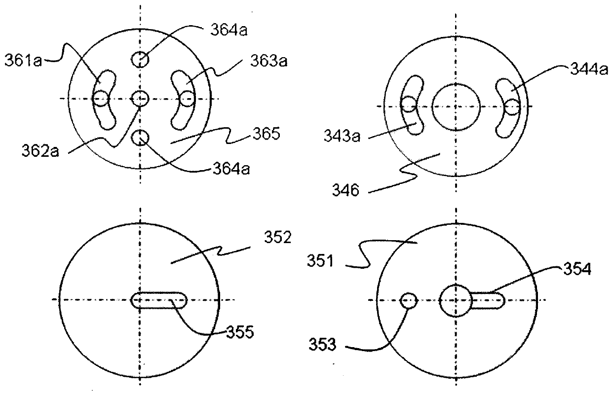
[0034] Figure 4 It is a diagram of the position relationship between the air channels and the grooves on the sealing surface of the rotary valve embodiment 2. In this embodiment, the air channels are symmetrically paired at 180 degrees. In this way, the rotor 35 makes one revolution and the refrigerator works for two weeks. , the advantage of this design is that the surface pressure is balanced, which is conducive to long life. Of course, more air passages and grooves can also be provided, so that the motor rotates once and the refrigerator works for 3 or more cycles.

[0035] Figure 5 Shown is t...


PUM


Abstract

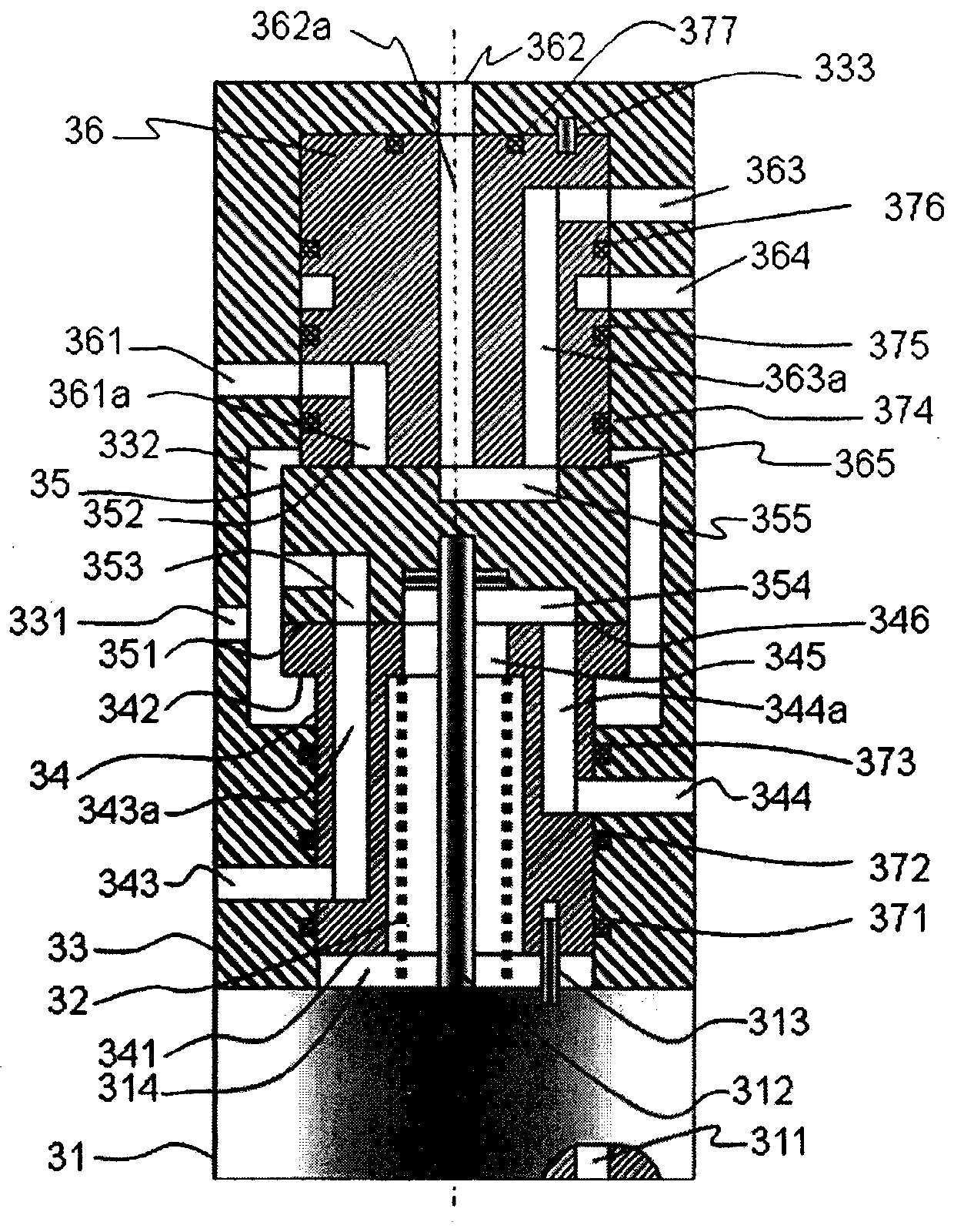
The invention relates to a refrigerator, in particular to a rotating valve for a pulse tube refrigerator. The rotating valve comprises a motor (31), a spring (32), a valve shell (33), a first stator (34), a rotor (35) and a second stator (36). The rotating valve is characterized in that sealing surfaces are arranged at two ends of the rotor (35), and the first stator (34) can axially and freely move, so that the first stator (34), the rotor (35) and the second stator (36) can be compressed together to form two sealing surfaces.

Description

technical field [0001] The invention relates to a pulse tube refrigerator, in particular to a rotary valve for a pulse tube refrigerator. Background technique [0002] Pulse tube refrigerator is a kind of gas refrigerator, which is mainly used in the low temperature field below 77K, and the working medium is mostly helium. The principle is that the gas expands in the pulse tube to do work and cool down. A vessel is an empty tube. Because the pulse tube refrigerator has no moving parts at low temperature, low vibration and high reliability, it has been widely valued. In the popular GM-type pulse tube refrigerator, there is a compressor supplying high-pressure gas, which enters the cold head through a rotary valve to expand to low-pressure refrigeration, and then returns to the compressor through a rotary valve to be compressed to high pressure. The cold head has no moving parts, resulting in high reliability. Rotary valves, on the other hand, are moving parts and must be ...

Claims


Application Information

Patent Timeline
Patent Type & Authority Patents(China)
IPC IPC(8): F16K11/074F16K3/30F25B9/14
CPCF16K3/314F16K11/074F25B9/145
Inventor 朱绍伟
Owner 朱绍伟
Learn More