
Output mechanism for water meter movement impeller boxes

A technology of output mechanism and core, which is applied in the direction of conveyor objects, transportation and packaging, metal processing, etc., can solve the problems of poor assembly quality and uniformity, low work efficiency, easy injury, etc., and achieve the effect of improving work efficiency

Active Publication Date: 2014-07-16
安徽格太信控科技有限公司
View PDF11 Cites 5 Cited by
  • Summary
  • Abstract
  • Description
  • Claims
  • Application Information

AI Technical Summary

Problems solved by technology

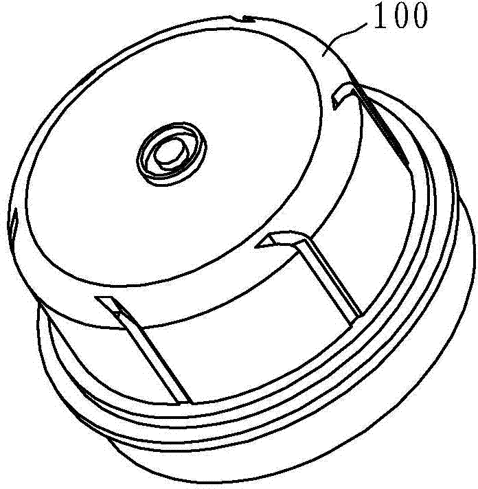
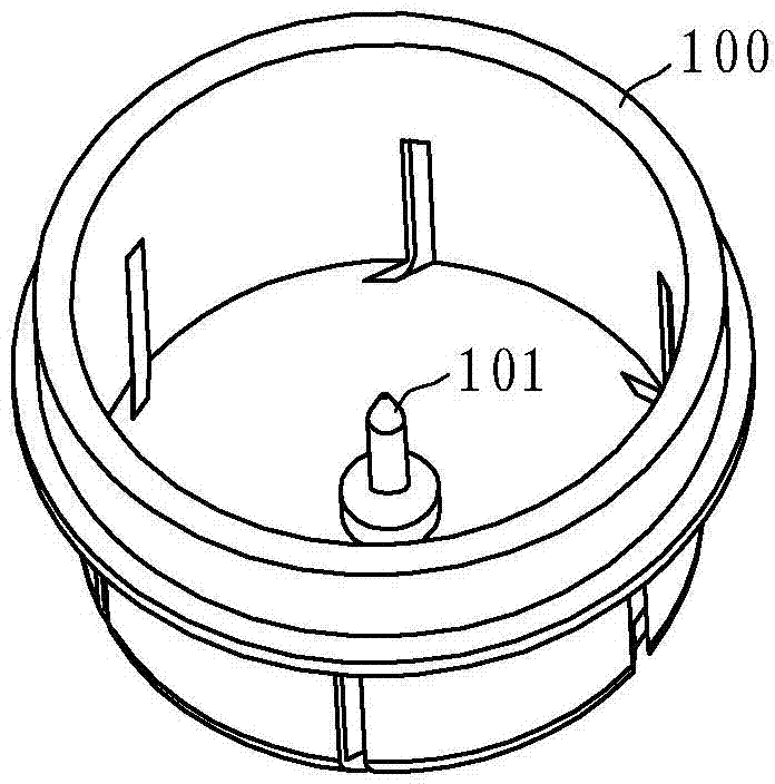
[0004] At present, the tip is usually manually pressed into the installation hole at the bottom of the impeller box. This installation method has the following disadvantages: firstly, it is difficult to grasp the magnitude of the pressure applied by hand, and it is difficult to control the depth of the tip; the direction of the pressure applied by hand is not accurate. , which may lead to deviations in the position of the top; therefore, the final assembly quality and assembly uniformity are poor. Secondly, it is inconvenient for workers to operate, labor-intensive, and easily injured; finally, due to the low degree of automation, the overall work efficiency Low, the work efficiency of skilled workers is difficult to break through the limit
Although this patent solves the automatic assembly process of the tip and the impeller box, after the assembly is completed, the removal of the impeller box from the positioning structure of the workbench still needs to be done manually, and the automation is not fully realized, and further improvement can be made

Method used


Image

  • Output mechanism for water meter movement impeller boxes
  • Output mechanism for water meter movement impeller boxes
  • Output mechanism for water meter movement impeller boxes

Examples


Embodiment Construction

[0022] The present invention will be further described in detail below in conjunction with the accompanying drawings and embodiments.

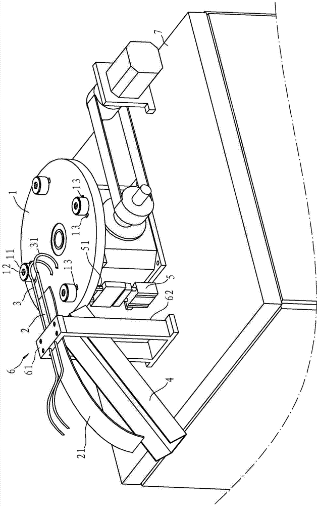
[0023] Such as image 3 and Figure 4 As shown, the output mechanism of the water meter movement leaf in this embodiment includes a worktable 7, a rotating disk 1, an ejection cylinder, a bracket 6, an air blowing mechanism 3, a baffle plate 2 and an output channel 4. The rotating disk 1 is arranged on the worktable 7 and can rotate intermittently under the drive of the motor 8. The upper end surface is evenly arranged along the circumferential direction with four mounting seats 11 for the leaf joint cover. The middle part of the mounting seat 11 has a The hollow channel 12 where the tip is inserted, and the rotating disc 1 is provided with through holes 13 on both sides of the mounting base 11 .

[0024] The ejector cylinder is located on the worktable 7, and the upper end has a push rod 51 that can stretch out the through hole 13 of the ro...


PUM


Abstract

The invention provides an output mechanism for water meter movement impeller boxes. The output mechanism is characterized by comprising a work table plate, a rotating plate, an ejector air cylinder, a blowing mechanism and an output channel. The rotating plate is arranged on the work table plate and can rotate in a gap mode under driving of a motor. The upper end face of the rotating plate is provided with a plurality of installation bases for the impeller boxes to cover in the circumferential direction. The middle of each installation base is provided with a hollow channel for a centre to be inserted. Moreover, the side edges, located on the installation bases, of the rotating plate are provided with through holes. The ejector air cylinder is arranged on the work table plate. The upper end of the ejector air cylinder is provided with an ejector rod which can vertically extend out of the through holes of the rotating plate upwards. The blowing direction of the blowing mechanism directly faces the installation bases. The output channel can bear the impeller boxes separated from the installation bases. Compared with the prior art, the output mechanism has the advantages that after being assembled, the impeller boxes can be smoothly and fast separated from the installation bases and can enter the output channel through cooperation of the ejector air cylinder and the blowing mechanism, the unloading process can be finished automatically, and the output mechanism is convenient and fast to use and greatly improves the work efficiency.

Description

technical field [0001] The invention relates to a water meter processing output structure, in particular to the output structure of the water meter leaf joint after the tip is assembled, and belongs to the technical field of water meter processing. Background technique [0002] The rotor-type water meter is a kind of speed-type water meter, which is widely used in the world. The metering mechanism of the rotor-type water meter is mainly composed of a gear box, an impeller box (leaf joint), an integral impeller, a top, an adjusting plate, etc., among which the gear box and the impeller box form the movement. The metering mechanism plays a key role in the metering performance and durability of the water meter. [0003] Patent No. ZL200710035843.5 Chinese Invention Patent "A Rotary Wing Water Meter" (authorized announcement No. CN100529681C) China discloses a water meter, its structure: the tip is installed at the center of the bottom of the impeller box, at the bottom of the ...

Claims


Application Information

Patent Timeline
IPC IPC(8): B23P19/02
CPCB23P19/02B65G47/78B65G47/80B65G47/82
Inventor 赵如松敖开才
Owner 安徽格太信控科技有限公司
Learn More