
electronic device

A technology for electronic devices and electronic cards, which is applied in electrical digital data processing, instruments, digital data processing components, etc., can solve the problems of large rotation space, inconvenient disassembly, and inability to apply to thin and light computers or servers, and achieves the ability to rotate in space. small effect

Active Publication Date: 2017-02-22
WISTRON CORP
View PDF5 Cites 0 Cited by
  • Summary
  • Abstract
  • Description
  • Claims
  • Application Information

AI Technical Summary

Problems solved by technology

However, it is inconvenient to disassemble by means of screw locking, especially when the interface card is set in a flat position (parallel to the main board), and the interface card is fixed by means of screw locking, during the process of installing or removing the interface card , often interfere with or collide with other electronic components in the computer or server
[0003] In the known technology, there is also a design of a single interface card locked by a rotating mechanism. However, this method requires a large rotating space and cannot be applied to thin and light computers or servers.

Method used


Image

  • electronic device
  • electronic device
  • electronic device

Examples


Embodiment Construction

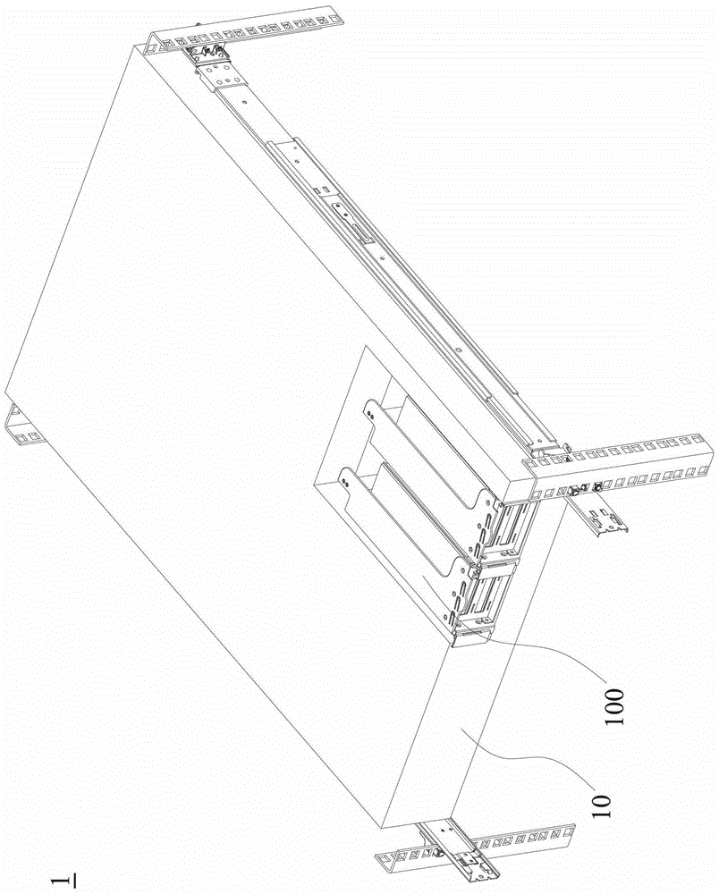
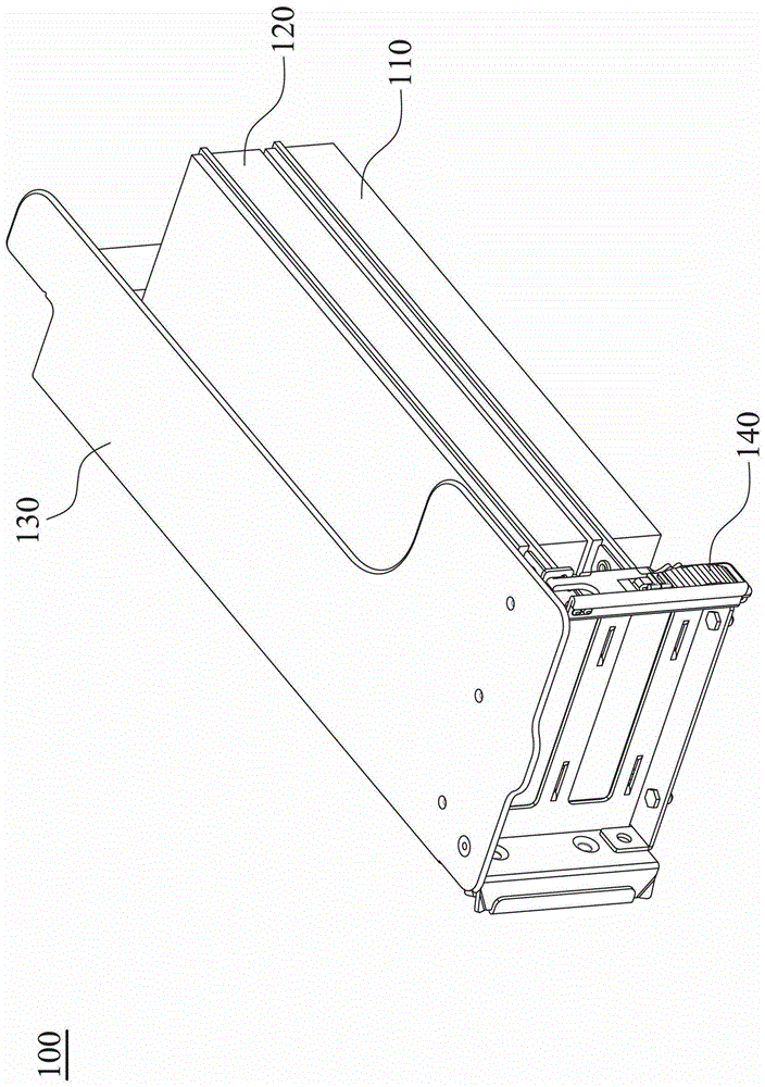
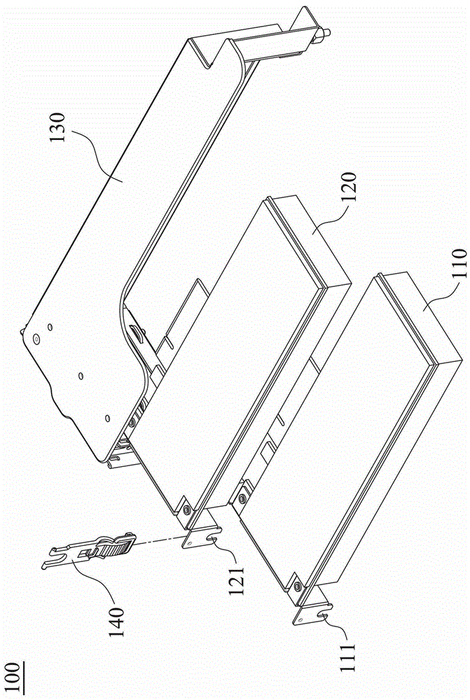
[0029] refer to figure 1 , which shows the electronic device 1 according to the embodiment of the present invention, including at least one card module 100 and a body 10 . The card insertion module 100 is detachably connected to the body 10 . And the motherboard (not shown) in the body 10 is electrically connected to the plug-in module 100 .

[0030] refer to Figure 2A as well as Figure 2B , Figure 2A A combination diagram showing the plug-in card module 100, Figure 2B An exploded view of the plug-in card module 100 is shown. The card insertion module 100 includes a first electronic card 110 , a second electronic card 120 , a bracket 130 and a locking mechanism 140 . The first electronic card 110 and the second electronic card 120 are detachably inserted into the bracket 130 . The locking mechanism 140 is pivotably disposed on the bracket 130 . In one embodiment, the first electronic card 110 and the second electronic card 120 are parallel to the motherboard in the...


PUM


Abstract

An electronic device comprises a card insertion module. The card insertion module comprises a bearing support, a first electronic card and a lock catch mechanism. A location portion is formed in the bearing support, the first electronic card is inserted into the bearing support in a detachable mode, the lock catch mechanism is arranged in the bearing support in a pivoting mode, and the lock catch mechanism pivots the bearing support between a first direction and a second direction. When the lock catch mechanism is located at the first direction, the lock catch mechanism can be shifted between the first position and the second position, and the extending direction of the lock catch mechanism is perpendicular to the surface of a first electronic card at the moment. The lock catch mechanism comprises a pivoting end and a clamping end, the pivoting end is pivoted on the bearing support. When the lock catch mechanism is located at the first position, the clamping end is clamped at the location portion. When the lock catch mechanism is located at the second position, the clamping end deviates from the location portion. The electronic device requires small space and is applicable to thin light computers or servers.

Description

technical field [0001] The present invention relates to an electronic device, in particular to a plug-in card module applied to a computer or a server. Background technique [0002] In computers or servers, interface cards are generally provided to expand the performance of the computers and servers. In a common design, a positioning portion is formed on the interface card, and the interface card is mainly fixed on the body of the computer or server by means of screw locking. However, it is inconvenient to disassemble by means of screw locking, especially when the interface card is set in a flat position (parallel to the main board), and the interface card is fixed by means of screw locking, during the process of installing or removing the interface card , often interfere or collide with other electronic components in the computer or server. [0003] In the known technology, there is also a design of a rotating mechanism to lock and lock a single interface card. However, t...

Claims


Application Information

Patent Timeline
Patent Type & Authority Patents(China)
IPC IPC(8): G06F1/16
Inventor 莫寒军朱重兴
Owner WISTRON CORP
Learn More