
Improved type gas detector

A gas detector, an improved technology, applied in the direction of instruments, measuring devices, scientific instruments, etc., can solve the problems that the gas to be detected cannot be sensed quickly, it is not easy to flow into the gas sensor vertically, and the sensitivity of the gas detector is affected, etc., to achieve rapid Inductive response, high inductive sensitivity, effect of enhanced inductive sensitivity

Active Publication Date: 2014-07-09
四川久远智能消防设备有限责任公司
View PDF4 Cites 1 Cited by
  • Summary
  • Abstract
  • Description
  • Claims
  • Application Information

AI Technical Summary

Problems solved by technology

[0004] Since the air inlet window 11 on the gas sensor opens upwards, it is vertically arranged; when the detected gas flows from the outer cover window on the outer cover to the air inlet window on the gas sensor, a lot of gas still circulates along the horizontal direction, and most of them are absorbed by the gas sensor. When the detected gas reaches the top of the gas sensor, the air inlet window 11 on the top of the gas sensor slides horizontally (flows through) (see also image 3 The gas flow schematic diagram in ), it is not easy to vertically flow into the upper air inlet window 11 of the gas sensor, because most of the detected gas is not detected by the sensitive body inside the gas sensor (the gas entering the air inlet window of the gas sensor Insufficient amount), so the existing gas detectors cannot quickly sense the gas to be detected. Most importantly, the sensitivity of the gas detector will be greatly affected, directly affecting the detection results

Method used


Image

  • Improved type gas detector
  • Improved type gas detector
  • Improved type gas detector

Examples


Embodiment 1

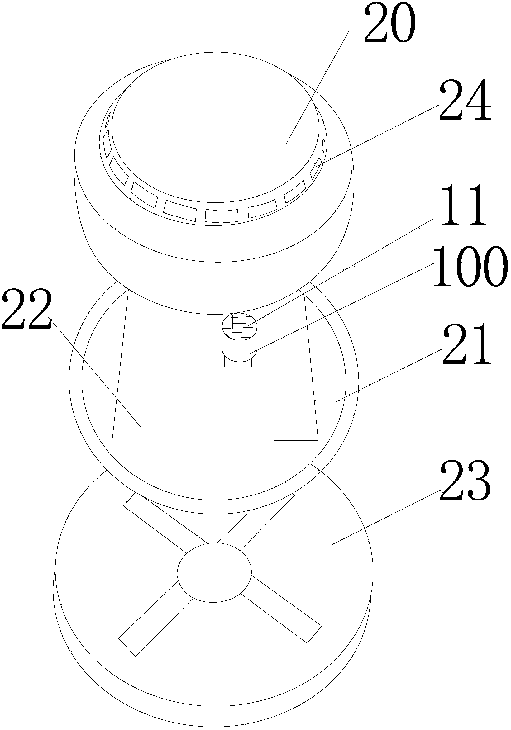
[0031] Embodiment 1 of the present invention provides an improved gas detector, which includes an outer cover 20 from top to bottom (attended Figure 4 ), middle gusset (not shown, same as figure 1 The structure of the prior art in) and the circuit core board ( Figure 4 not shown) and mounting base ( Figure 4 not shown); also includes a gas sensor mounted on the circuit core board of the middle gusset plate, the gas sensor is connected with the integrated circuit on the circuit core board; the diameter of the air inlet window at the top of the gas sensor is d; the outer cover is provided with a plurality of outer cover windows along the circumferential direction of the outer cover wall (the main improvement structure of the improved gas detector provided by the embodiment of the present invention is the improvement of the outer cover 20, and its inner bottom surface contains a plurality of V Shaped flow-guiding baffles constitute structural components, and the middle gusse...


PUM

PropertyMeasurementUnit
Thicknessaaaaaaaaaa
Opening widthaaaaaaaaaa
Thicknessaaaaaaaaaa

Abstract

The invention discloses an improved type gas detector. The improved type gas detector comprises an outer cover, a middle buckle plate, a circuit core plate and a mounting base in sequence from top to bottom, wherein the circuit core plate and the mounting base are mounted in the middle buckle plate. The improved type gas detector further comprises a gas sensitive sensor mounted on the circuit core plate of the middle buckle plate; the gas sensitive sensor is connected with a circuit integrated on the circuit core plate; the diameter of an air inlet window on the top of the gas sensitive sensor is d; the outer cover is provided with a plurality of outer cover windows along the peripheral direction of an outer cover wall; after the outer cover is assembled with the gas sensitive sensor on the circuit core plate of the middle buckle plate, the inner surface of the outer cover is provided with a plurality of V-shaped flow guide flow-stopping sheets which take the assembled gas sensitive sensor as the center and are arranged along the peripheral direction at intervals; openings of the plurality of V-shaped flow guide flow-stopping sheets are opposite to the air inlet window on the gas sensitive sensor at the central position. The improved type gas detector can realize rapid triggering induction detection and the induction time is shortened; the improved type gas detector has the high induction sensitivity, is simple in structure, and is convenient and practical.

Description

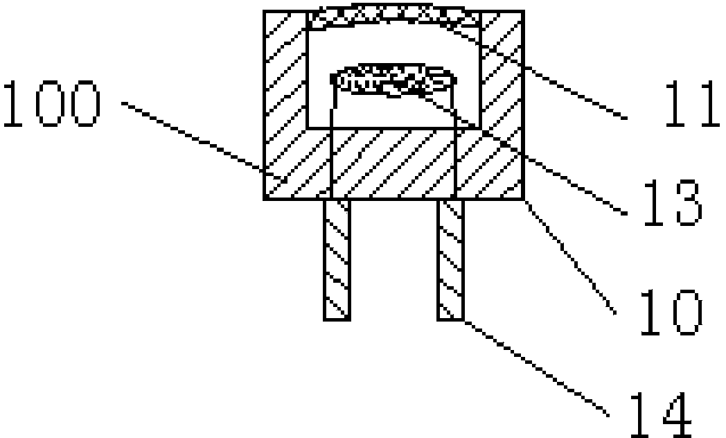
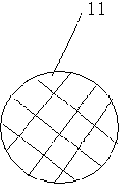
technical field [0001] The invention relates to the field of gas detection equipment, in particular to an improved gas detector. Background technique [0002] In existing gas detectors, the core device mainly used to detect gas is a gas sensor 100 (see figure 1 ); it is arranged inside the gas detector, and its external structure is a cylindrical structure, and a circular air inlet window 11 with a diameter of d is provided on the top of the cylinder and the inner cavity of the sensor housing 10, and the air inlet window is equipped with an aperture Tens of microns of stainless steel dust screen (i.e. the structure shown by the cross grid near the air intake window 11, or refer to Figure 1a The structure at the air intake window 11), the inner cavity of the sensor housing 10 is also provided with a sensitive body 13, and the two ends of the sensitive body 13 respectively stretch out from the bottom of the sensor housing and are connected with the sensor pins 14. [0003] ...

Claims


Application Information

Patent Timeline
IPC IPC(8): G01N33/00
Inventor 戴建新刘利
Owner 四川久远智能消防设备有限责任公司
Learn More