Eureka AIR delivers breakthrough ideas for toughest innovation challenges, trusted by R&D personnel around the world.

Suspended single rotor gas flow meter

A gas flow meter, single rotor technology, applied in fixed measurement chambers and other directions, can solve the problems of rotor not fixed, rotor opening and positioning baffle friction, rotor sinking, etc., to improve service life and accuracy, reduce Effects of pressure loss and frictional resistance reduction

Active Publication Date: 2016-10-05
山西霖泉仪表有限公司
View PDF6 Cites 0 Cited by
  • Summary
  • Abstract
  • Description
  • Claims
  • Application Information

AI Technical Summary

Problems solved by technology

[0003] The present invention provides a suspended single-rotor gas flowmeter in order to solve the problems of serious friction between the rotor opening and the positioning baffle of the rotary-floating single-rotor flowmeter and the problem that the rotor is not positioned and fixed so that the rotor naturally sinks

Method used


Image

  • Suspended single rotor gas flow meter
  • Suspended single rotor gas flow meter
  • Suspended single rotor gas flow meter

Examples


Embodiment Construction

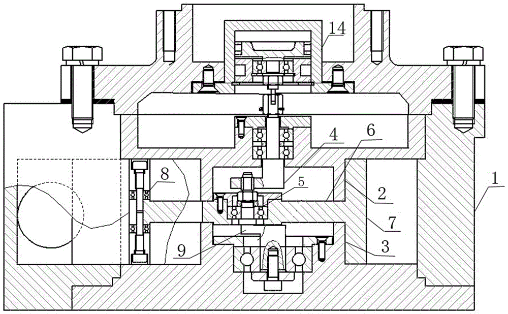
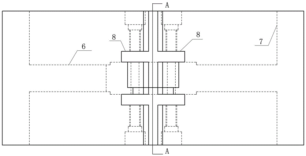
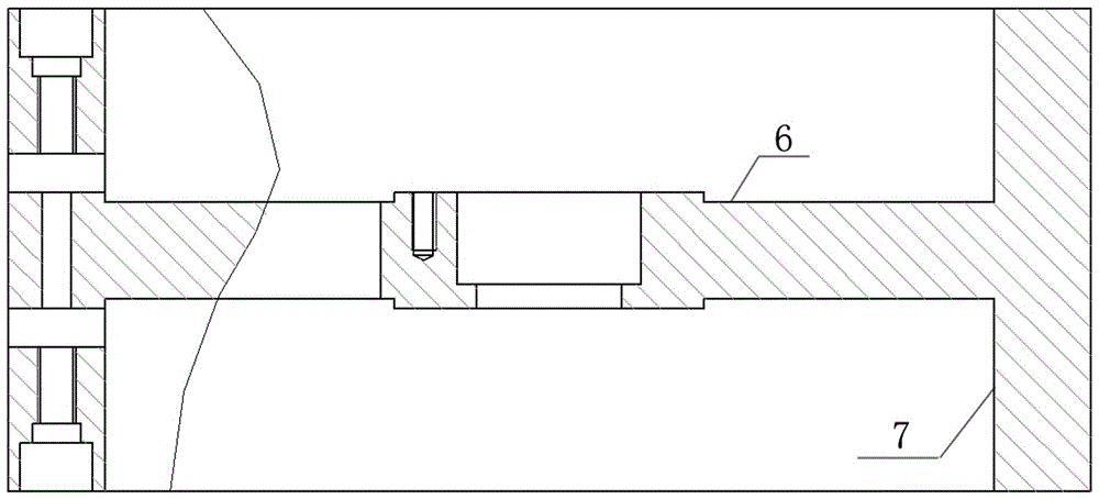
[0013] Suspended single-rotor gas flowmeter, including a hollow housing 1 and a rotor arranged in the hollow housing, the upper and lower positioning cylinders 2 and 3 with corresponding positions and the same outer diameter are fixed on the top and bottom of the hollow housing, and the upper positioning Inside the cylinder 2 and the lower positioning cylinder 3 are respectively provided with an upper crankshaft 4 formed by connecting a horizontal axis and a vertical axis, and a lower crankshaft 9 formed by connecting a first vertical axis, a second vertical axis, and a horizontal axis. The vertical axis of the crankshaft is arranged in the upper positioning cylinder 2, the second vertical axis of the lower crankshaft 9 is arranged in the lower positioning cylinder 3, the vertical axis of the upper crankshaft and the second vertical axis of the lower crankshaft 9 are coaxial, and the rotor Comprising a horizontal circular plate 6 and a circular ring 7 fixed around the horizonta...


PUM


Abstract

The invention relates to a volume-type gas flowmeter for measuring gas flows, in particular to a gas flowmeter with a suspended single rotor. The gas flowmeter comprises a hollow shell and a rotor arranged in the hollow shell, wherein the rotor comprises a horizontal round plate and a round ring fixed with the periphery of the horizontal round plate; one side of the round ring is provided with an opening which extends onto the horizontal round plate and forms a conical opening on the same; bearings are fixed on a ring body and on two sides of the opening of the round ring; stop plates are fixed between the hollow shell and an upper positioning cylinder and between the hollow shell and a lower positioning cylinder; and outer rings of the bearings on the ring body at the position of the opening are in contact with the stop plates. When the rotor moves, frictional resistance among the rotor and the stop plates is lowered, so that service life of the gas flowmeter is prolonged, and the precision of the gas flowmeter is increased.

Description

technical field [0001] The invention relates to a volumetric gas flowmeter for measuring gas flow, in particular to a suspended single-rotor gas flowmeter. Background technique [0002] At present, there is a rotary-floating single-rotor flowmeter. Although it has the advantages of simple structure, convenient maintenance, easy processing, and not easy to jam among positive displacement flowmeters, there is direct friction between the rotor opening and the positioning baffle. The surface is large, and the rotor is not positioned and fixed, resulting in the natural sinking of the rotor, which not only wears seriously, but also forms a certain resistance. Without liquid lubrication, it is impossible to measure the gas, which limits the scope of application. Contents of the invention [0003] In order to solve the problems of serious friction between the rotor opening and the positioning baffle plate of the rotating-floating single-rotor flowmeter and the problem that the rot...

Claims


Application Information

Patent Timeline
Patent Type & Authority Patents(China)
IPC IPC(8): G01F11/28
Inventor 张六祥李太平张志强赵一波
Owner 山西霖泉仪表有限公司
Why Eureka
Eureka Blog
Learn More