
Planar piezoelectric-driven platform with three degrees of freedom and method for driving planar piezoelectric-driven platform to move

A piezoelectric drive and piezoelectric drive technology, applied in machine/stand, supporting machine, mechanical equipment, etc., can solve the problem of small working space of positioning platform, low positioning accuracy of plane motion platform, and it is difficult for the platform to meet the requirements of nano-level positioning. and other problems to achieve the effect of avoiding hinge gap error, simple structure and high resolution

Active Publication Date: 2014-07-09
NANJING UNIV OF AERONAUTICS & ASTRONAUTICS
View PDF6 Cites 9 Cited by
  • Summary
  • Abstract
  • Description
  • Claims
  • Application Information

AI Technical Summary

Problems solved by technology

[0002] At present, the hinge gap error is the main reason for the low positioning accuracy of the planar motion platform, so it is difficult for the platform to meet the nano-level positioning requirements
Although the gap error between the hinges can be reduced to a certain extent by using the compliant mechanism of the flexible hinge, but limited by the limited flexible deformation of the flexible hinge, the working space of the positioning platform is small (generally only micron-level working space can be realized)

Method used


Image

  • Planar piezoelectric-driven platform with three degrees of freedom and method for driving planar piezoelectric-driven platform to move
  • Planar piezoelectric-driven platform with three degrees of freedom and method for driving planar piezoelectric-driven platform to move
  • Planar piezoelectric-driven platform with three degrees of freedom and method for driving planar piezoelectric-driven platform to move

Examples


Embodiment Construction

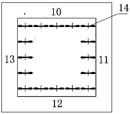
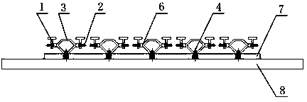
[0027] The working principle and specific implementation of the planar three-degree-of-freedom piezoelectric drive platform will be described in detail below by using 16 piezoelectric drive modules (ie, n=4) for excitation.

[0028] Such as figure 1 , figure 2 , image 3 As shown, the planar three-degree-of-freedom piezoelectric driving platform of the present invention is composed of a piezoelectric driving module, an elastic plate, a functional platform and a static platform. The 16 piezoelectric drive modules are arranged in a square on the elastic plate, wherein each side of the square is composed of 5 piezoelectric drive modules, which are respectively connected to the upper surface of the elastic plate by fixing bolts; the described function The platform is a square rigid plate with uniform material, which is connected to the piezoelectric drive module by welding; the static platform is in direct contact with the lower surface of the elastic plate; by applying a speci...


PUM


Abstract

The invention discloses a planar piezoelectric-driven platform with three degrees of freedom and a method for driving the planar piezoelectric-driven platform to move, and belongs to the field of precision driving technologies. The planar piezoelectric-driven platform comprises a function platform, piezoelectric driving modules, an elastic plate and a fixed platform. The function platform is used for carrying and positioning objects and is connected with the piezoelectric driving modules; each piezoelectric driving module comprises two piezoelectric stacks, a displacement amplification mechanism, connecting plates, a fixing bolt and pretension force bolts; the elastic plate is connected with the piezoelectric driving modules by the fixing bolts; the fixed platform is used as a support platform for the elastic plate and is arranged on the lower side of the elastic plate. The planar piezoelectric-driven platform and the method have the advantages that specific driving signals are respectively transmitted to the piezoelectric driving modules which are arranged on the elastic plate to form a square respectively, so that traveling waves which run in different directions can be stimulated on the elastic plate, and the function platform with three degrees of freedom can move; errors such as hinge gaps due to traditional mechanical transmission can be prevented, and a large-stroke and high-precision target positioning effect can be realized.

Description

technical field [0001] The invention belongs to the technical field of precision driving, and relates to a driving positioning device, in particular to a plane three-degree-of-freedom piezoelectric driving platform. Background technique [0002] At present, the hinge gap error is the main reason for the low positioning accuracy of the planar motion platform, so it is difficult for the platform to meet the nano-level positioning requirements. Although the gap error problem between hinges can be reduced to a certain extent by using the compliant mechanism of the flexible hinge, but limited by the limited flexible deformation of the flexible hinge, the working space of the positioning platform is small (generally only micron-level working space can be realized) . Therefore, in view of the above two technical problems, the present invention utilizes the precise drive output of the piezoelectric stack and cooperates with the displacement amplification mechanism to realize the tr...

Claims


Application Information

Patent Timeline
IPC IPC(8): F16M11/06F16M11/18F16M11/24
Inventor 张泉章洪轩季瑞南金家楣王亮
Owner NANJING UNIV OF AERONAUTICS & ASTRONAUTICS
Learn More