Inflating device with air storage barrel

A technology of air storage barrels and cylinders, which is applied in the direction of pump devices, liquid variable-capacity machines, variable-capacity pump components, etc., and can solve problems such as overall operation troubles, time-wasting, and inaccurate handling

Active Publication Date: 2014-07-09
BETO ENG & MARKETING
View PDF7 Cites 15 Cited by
  • Summary
  • Abstract
  • Description
  • Claims
  • Application Information

AI Technical Summary

Problems solved by technology

[0002] The prior art is just as shown in the U.S. No. 6,883,565 patent, such as its image 3 As shown, it mainly rotates 360 degrees through the valve body to switch the three operation modes of external air supply from the inflator, external air supply from the air storage tank, or external air supply from the inflator to the air storage tank. These three operating modes exist independently Therefore, in addition to controlling the force and position of the rotating valve body by hand, the user must also visually observe the valve body to reach the desired fixed point position. It can be seen that it can only be completed through hand-eye coordination, and the rank is at least There are three, so the overall operation is very troublesome, and the hand is often inaccurate in controlling the rotation position of the valve body, and it is very difficult to control the force. It is necessary to adjust the position repeatedly, wasting a lot of time, especially in an emergency, which is even more annoying. It is really a big failure in the use of the structure, causing users to be unable to switch as they wish. Many related manufacturers have spared no effort in research and development, but so far there is still no better structure to overcome the above-mentioned shortcomings.

Method used


Image

  • Inflating device with air storage barrel
  • Inflating device with air storage barrel
  • Inflating device with air storage barrel

Examples


Embodiment Construction

[0060] In order to further explain the technical solution of the present invention, the present invention will be described in detail below through specific examples.

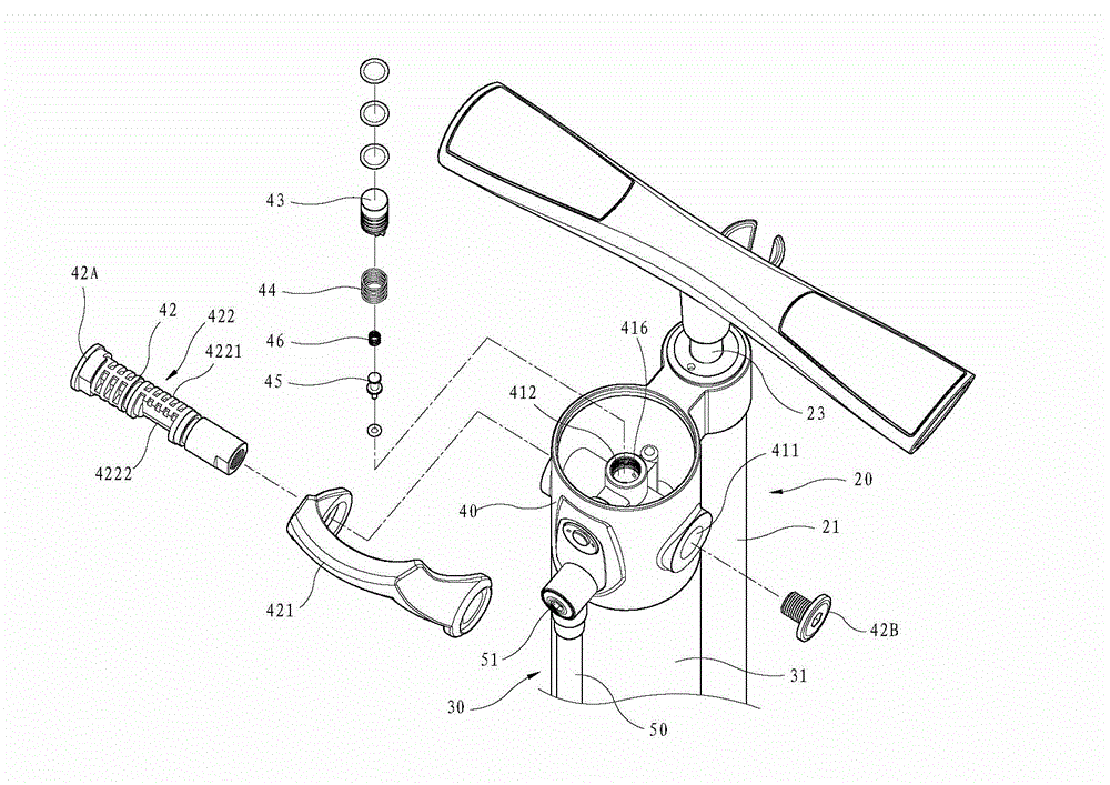
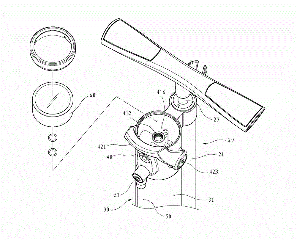
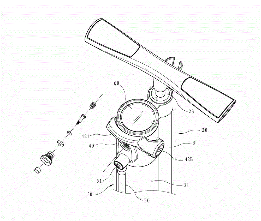
[0061] Please refer to Figure 1 to Figure 8 , the present invention includes:

[0062] A carrier 10, which is provided with a U-shaped approach 11 communicating with the inside and outside, and a socket 12 is provided at one end of the opposite approach 11, and a one-way valve 13 is installed;

[0063] An inflating device 20 has a hollow cylinder 21, the bottom of which is fixed to the socket 12 of the carrier 10, and a piston 22 is slidably arranged in the cylinder 21, which can be driven by a linkage rod 23 to move in the cylinder. Agitate the gas in 21, so that the pressurized gas can enter the approach 11 through the one-way valve 13;

[0064] A gas storage barrel 30, which has a barrel body 31 whose bottom end is airtightly fixed on the stage 10, a top plate 32 that closes the top edge of the barrel bod...


PUM


Abstract

The invention relates to an inflating device with an air storage barrel. The inflating device with the air storage barrel is arranged on a carrier table, and the inflating device and the air storage barrel are in a parallel air supply configuration mode through a control valve; the control valve is coupled to a shaft rod, the shaft rod is externally connected with an force exerting unit and provided with a cam with a first area and a second area, and the control valve is provided with a main hole opposite to the cam, a air valve communicated with the air storage barrel, an air inlet passage for air feeding of the inflating device, and an air outlet passage for supplying air outwards; the main hole is slidingly matched with a slider, the slider elastically abuts against the cam, and a valve is elastically hung on the slider; the force exerting unit can drive the cam to be positioned at a first angle and a second angle, when the cam is at the first angle, the first area drives the slider to a first position to communicate the air inlet passage and the air outlet passage, the valve closes the air valve, and further the inflating device can be in an air outlet passage air supply mode; when the cam is at the second angle, the second area drives the slider to a second position, the slider closes the air outlet passage, the valve opens the air valve, so that the air valve can be communicated with the air inlet passage, and further the inflating device can be in a storage barrel air supply mode.

Description

technical field [0001] The invention provides a technique for integrating an inflating device and an air storage tank, and specifically refers to an inflating device with an air storage tank. Background technique [0002] The prior art is just as shown in the U.S. No. 6,883,565 patent, such as its image 3 As shown, it mainly rotates 360 degrees through the valve body to switch the three operation modes of external air supply from the inflator, external air supply from the air storage tank, or external air supply from the inflator to the air storage tank. These three operating modes exist independently Therefore, in addition to controlling the force and position of the rotating valve body by hand, the user must also visually observe the valve body to reach the desired fixed point position. It can be seen that it can only be completed through hand-eye coordination, and the rank is at least There are three, so the overall operation is very troublesome, and the hand is often in...

Claims


Application Information

Patent Timeline
IPC IPC(8): F04B41/02F04B39/10F04B39/00
Inventor 王罗平
Owner BETO ENG & MARKETING
Why Eureka
Try Eureka