Rotary single-arm crane

A rotary, single-arm technology, applied in the direction of load hanging components, track systems, cranes, etc., can solve the problems of long driving distance, low work efficiency, and small number of driving, and achieve high speed, reduce labor intensity, and short travel Effect

Inactive Publication Date: 2014-07-09
RUSHAN ZHENXING CAST STEEL
View PDF0 Cites 4 Cited by
  • Summary
  • Abstract
  • Description
  • Claims
  • Application Information

AI Technical Summary

Problems solved by technology

But compared to the huge number of machine tools, the number of driving is very small, the driving distance is long, the lifting speed is slow, and the work efficiency is low

Method used


Image

  • Rotary single-arm crane

Examples


Embodiment Construction

[0011] The present invention will be further described below in conjunction with accompanying drawing:

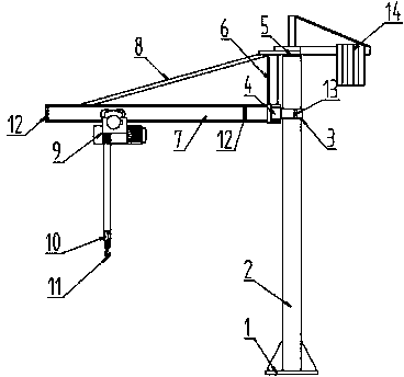
[0012] Such as figure 1 As shown, the present invention relates to a rotary single-arm crane, which is provided with a base 1, a column 2, a rotating shaft 5, a raceway 3, a support roller 4, a support plate 6, a beam 7, a tie bar 8, an electric hoist 9, and a pulley 10. The hook 11 and the counterweight iron 14 are characterized in that the base 1 and the lower end of the column 2 are welded together, the base 1 is fixed on the ground by bolts, the upper end of the support plate 6 is fixed with the rotating shaft 5, and the lower end is equipped with The support roller 4, the support roller 4 is installed on the raceway 3 and rolls around the column 2, the raceway 3 is fixed on the column 2, the end of the beam 7 close to the column 2 is welded on the support plate 6, and the other end is connected to the support plate through the tie bar 8 The upper ends of 6 are connect...


PUM


Abstract

The present invention relates to a rotary single-arm crane, which comprises a base, a vertical column, a rotary shaft, a raceway, a support roller, a support plate, a cross beam, an electric hoist, a pulley, a counter weight iron and other components, and is characterized in that the base and the lower end of the vertical column are integratedly welded, the base is fixed on the ground through a bolt, the upper end of the support plate and the rotary shaft are fixed, the lower end is provided with the support roller, the support roller is arranged on the raceway and rolls around the vertical column, the cross beam is welded on the support plate, the rotary shaft is arranged on the upper end of the vertical column and rotates around the vertical column, the electric hoist is placed on the cross beam through the roller to move, the lower end is provided with the pulley, the pulley is arranged on a lifting steel wire rope, and the counter weight iron is arranged on the other side of the vertical column and is positioned opposite to the cross beam. The rotary single-arm crane has advantages of short stroke, high speed, high efficiency and the like.

Description

technical field [0001] The invention relates to a lifting transport device, in particular to a rotary single-arm crane. Background technique [0002] At present, in machining workshops, operators often need to load and unload workpieces on machine tools. Workpieces with small weights are still mostly carried manually, and the labor intensity of workers is high, and there are potential safety hazards. Workpieces with large mass are difficult to carry manually, so they are all lifted by crane. But compared to the huge number of machine tools, the number of driving is very small, the driving distance is long, the lifting speed is slow, and the work efficiency is low. Therefore, there is an urgent need for a highly efficient lifting and transporting device to meet the actual needs of production. Contents of the invention [0003] The technical problem to be solved by the present invention is to overcome the deficiencies of the above-mentioned prior art, and provide a rotary...

Claims


Application Information

Patent Timeline
Patent Type & Authority Applications(China)
IPC IPC(8): B66C23/16B66C23/94B66C7/16
Inventor 王福振林国毅姜元昌
Owner RUSHAN ZHENXING CAST STEEL
Why Eureka
Try Eureka