Plate spring suspension vehicle self-weighing system
A technology of leaf springs and vehicles, which is applied in the direction of signal devices, etc., can solve the problems of increasing loading and weighing costs, reducing transportation efficiency, etc.
- Summary
- Abstract
- Description
- Claims
- Application Information
AI Technical Summary
Problems solved by technology
Method used
Image
Examples
example 1
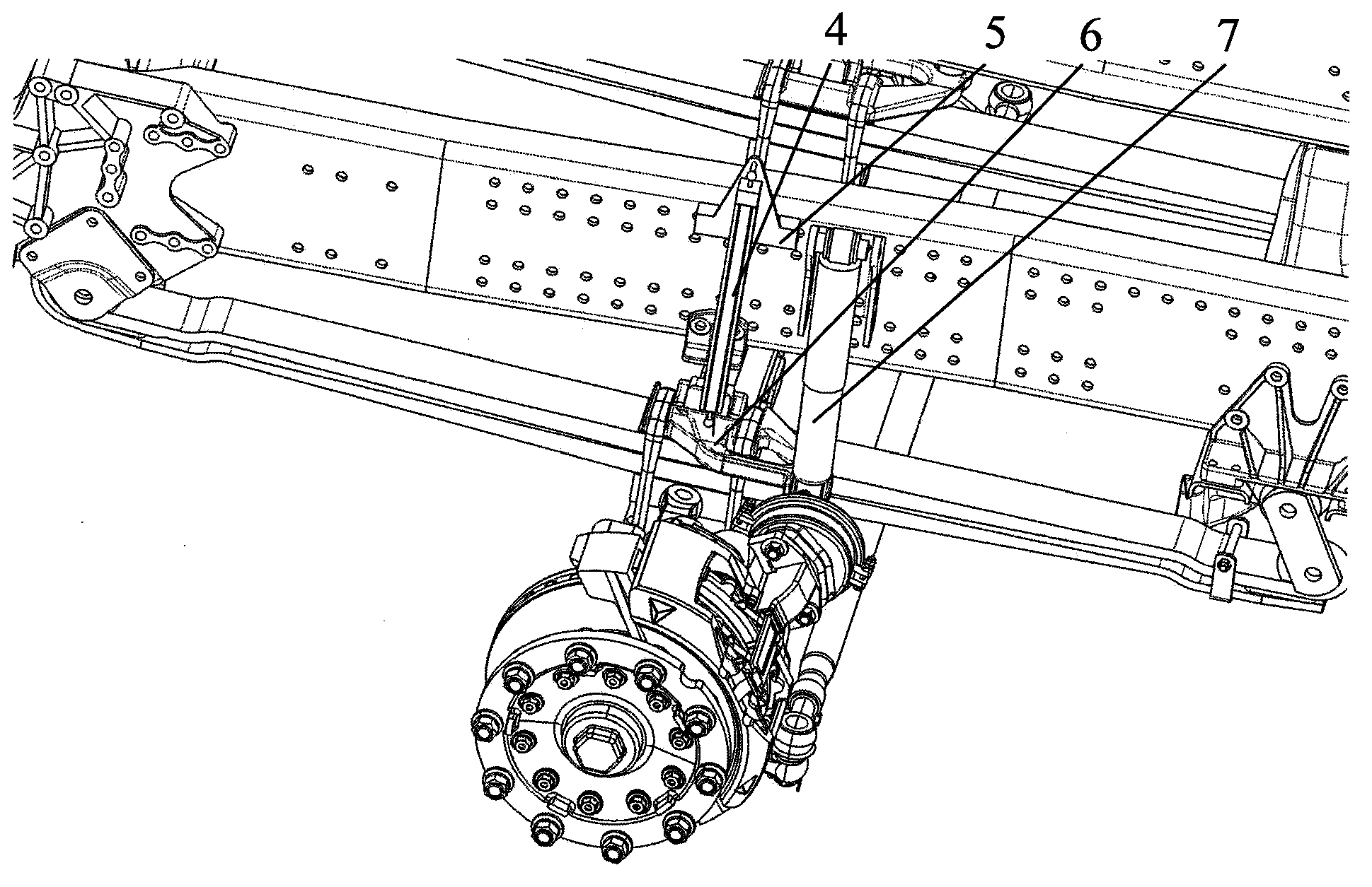
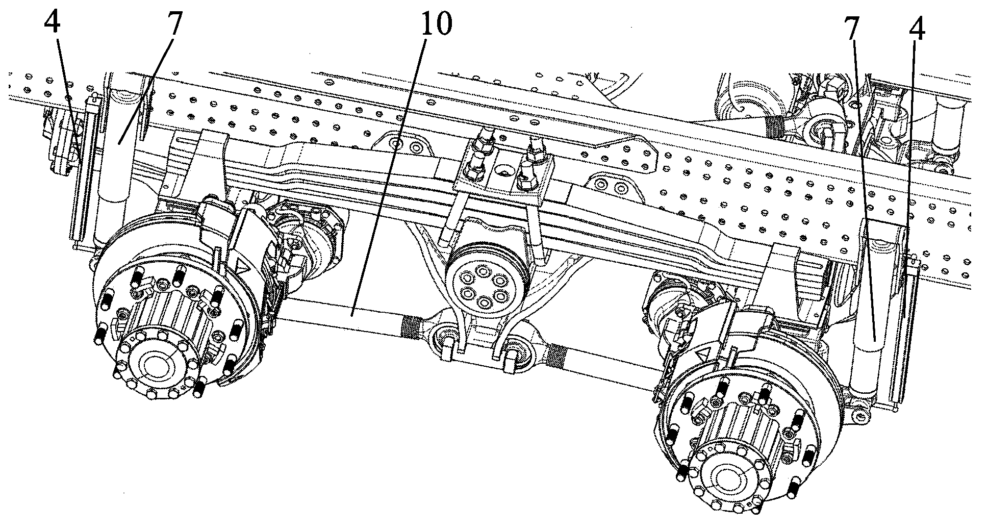
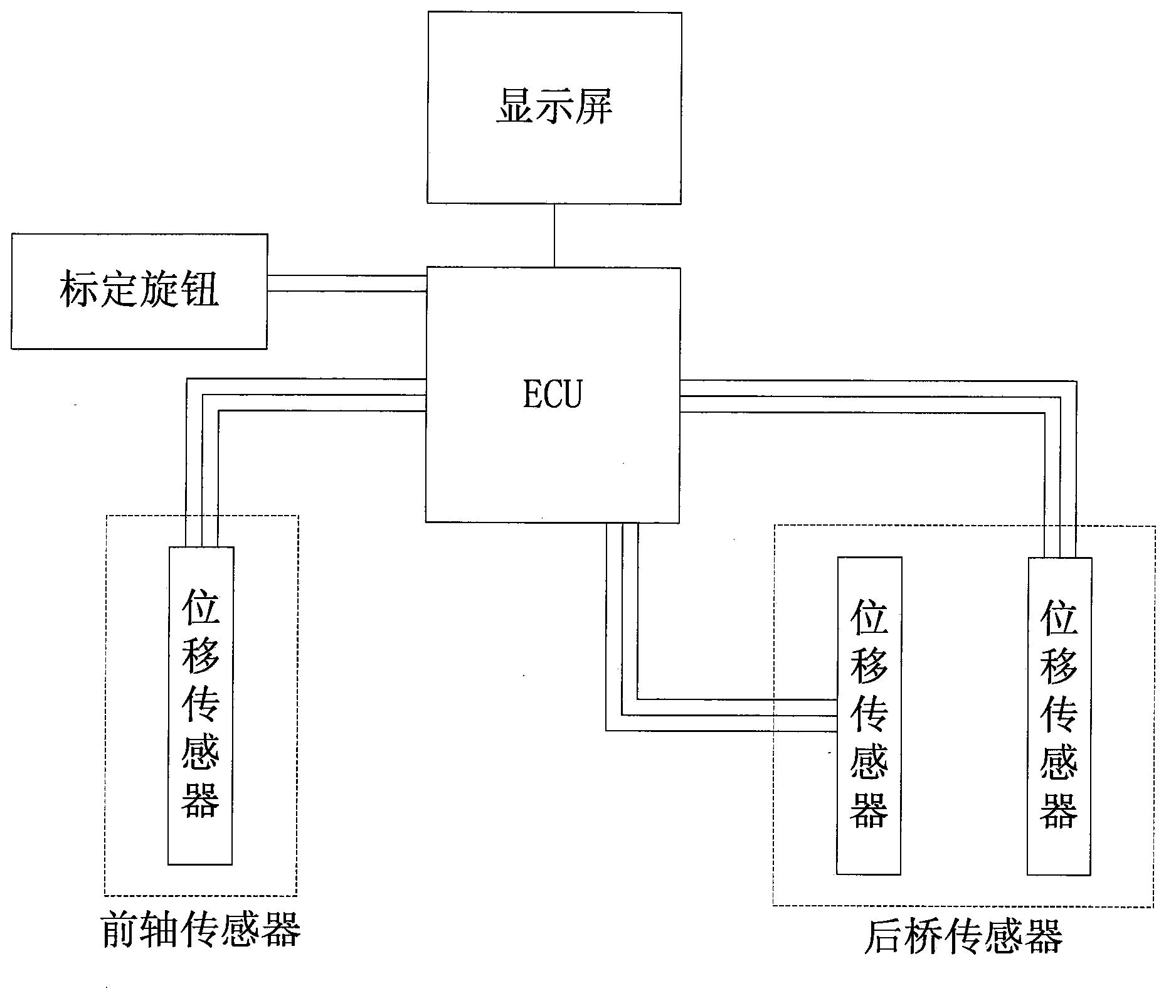
[0026] Example 1: see figure 1 , figure 2 and image 3 , a self-weighing system for a leaf spring suspension vehicle, including a displacement sensor and a mounting bracket, an electronic control unit (ECU), a display screen, a calibration knob and a connecting wire harness. Its installation form is: in the front suspension, such as figure 1 As shown, the displacement sensor 4 is installed between the displacement sensor upper bracket 5 and the leaf spring pressure plate 6, and the displacement sensors 4 are respectively hinged thereto. When the weight of the vehicle changes during the loading process, the leaf spring deforms under the load, and the middle part of the leaf spring will move up relative to the frame, and the deformation of the leaf spring can be obtained through the displacement sensor; in the rear balance suspension, such as figure 2 As shown, the upper end of the displacement sensor 4 (the main part of the displacement sensor) is hinged with the upper bra...
example 2
[0028] Example 2: see figure 1 , figure 2 and Figure 4 . figure 1 and figure 2 The layout is similar to Example 1. Figure 4 It can be seen that there are 4 displacement sensors 4 in total, of which there are two on the front axle, two on the balance suspension of the rear axle, and image 3 Compared with the front axle, there is one more front axle. This is because the vehicle with the drive form 8×4 has two front axles and leaf spring suspension structures. Vehicles, figure 1 The structure shown has two sets, arranged front and back on the vehicle frame assembly 2, figure 2 The structure shown has a set, consistent with a drive form 6×4 vehicle. so Figure 4 There are 4 displacement sensors in total. When the system is working, the ECU needs to receive the signals of these four displacement sensors and perform digital-to-analog conversion. At this time, the calibration of the system needs to flash in the program corresponding to the drive type 8×4 in advance, a...
PUM
 Abstract
Description
Claims
Application Information
 - R&D
- Intellectual Property
- Life Sciences
- Materials
- Tech Scout
- Unparalleled Data Quality
- Higher Quality Content
- 60% Fewer Hallucinations
Browse by: Latest US Patents, China's latest patents, Technical Efficacy Thesaurus, Application Domain, Technology Topic, Popular Technical Reports.
© 2025 PatSnap. All rights reserved.Legal|Privacy policy|Modern Slavery Act Transparency Statement|Sitemap|About US| Contact US: help@patsnap.com


