
Micron-scale inverse magnetostrictive driver and method of use

A technology of inverse magnetostriction and drive, applied in the direction of piezoelectric effect/electrostriction or magnetostriction motor, generator/motor, electrical components, etc., can solve the problem of current heat loss and magnetic permeability of magnetostrictive materials Low energy consumption, high energy consumption and other issues, to achieve the effect of stable work and suitable for high-precision positioning

Inactive Publication Date: 2016-09-28
ZHEJIANG SCI-TECH UNIV
View PDF8 Cites 0 Cited by
  • Summary
  • Abstract
  • Description
  • Claims
  • Application Information

AI Technical Summary

Problems solved by technology

The disadvantage of piezoelectric ceramics is that the material itself is relatively brittle, and the tangential load capacity is limited
The disadvantage of this driving method is high energy consumption and high temperature, and the magnetic permeability of magnetostrictive materials is usually low, which requires more ampere-turns to drive, and the current in the coil will cause heat loss
Moreover, most of the currently used magnetostrictive actuators are only for single use, and cannot achieve large stroke control by stacking multiple pieces like piezoelectric ceramics.

Method used


Image

  • Micron-scale inverse magnetostrictive driver and method of use
  • Micron-scale inverse magnetostrictive driver and method of use
  • Micron-scale inverse magnetostrictive driver and method of use

Examples


Embodiment 1

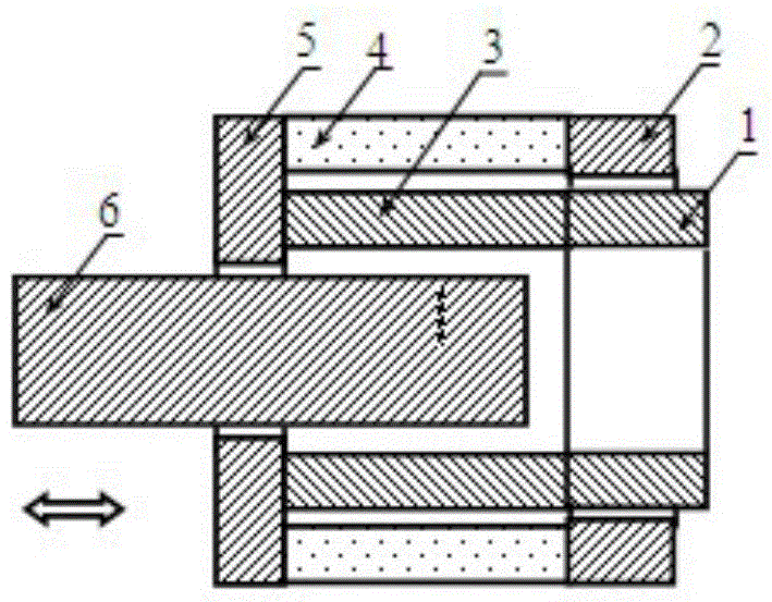
[0022] Embodiment 1, figure 1 , image 3 with Image 6 Provided is a micron-scale magnetostrictive actuator and a use method; a micron-scale magnetostrictive actuator includes a driver and a mover iron core 6 . The driver includes the end iron-gallium alloy magnetic core 1, the end permanent magnet magnetic core 2, the iron-gallium alloy 3, the magnet 4 (permanent magnet as an example) and the base magnetic core 5; the end iron-gallium alloy magnetic core 1 An iron-gallium alloy 3 is arranged between the base and the base magnetic core 5; a magnet 4 is arranged between the end permanent magnet magnetic core 2 and the base magnetic core 5. The iron-gallium alloy magnetic core 1 at the end, the iron-gallium alloy 3 and the base magnetic core 5 are provided with the mover iron core 6; the magnet 4 is axially magnetized; the magnet 4, the base magnetic core 5, the iron-gallium alloy 3, the end The iron-gallium alloy magnetic core 1 at the end and the permanent magnet magnetic c...

Embodiment 2

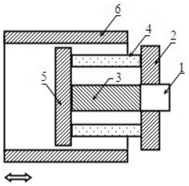
[0035] Embodiment 2, figure 2 , Figure 4 with Figure 5 A micron-scale magnetostrictive actuator is given, the end permanent magnet magnetic core 2 and the magnet 4 are set on the end iron-gallium alloy magnetic core 1 and the iron-gallium alloy 3; the permanent magnet magnetic core 2 and the magnet 4 Put on the mover iron core 6. The magnet 4 is axially magnetized, and through axial magnetization, a magnetic circuit I7 is formed on the base magnetic core 5, the iron-gallium alloy 3 and the end iron-gallium alloy magnetic core 1; the base magnetic core 5, the mover iron core 6 and the magnetically permeable core 2 form a magnetic circuit II8.

[0036] In actual use, a plurality of drivers are connected in series and used in conjunction with a single mover core 6 .

[0037] In actual use, the steps and principles of use are exactly the same as those in Embodiment 1.

[0038] When selecting the magnetostrictive material mentioned above, you can use Terfenol (the earliest ap...


PUM


Abstract

The invention discloses a micron order converse magnetostriction driver which comprises a driver body and an active cell iron core (6). The micron order converse magnetostriction driver is characterized in that the driver body comprises a magnet (4) and iron-gallium alloy (3); a magnetic circuit I (7) is formed by the magnet (4) and the iron-gallium alloy (3) through a permeability magnetic material; a magnetic circuit II (8) is further formed by the magnet (4) and the active cell iron core (6) through a permeability magnetic material.

Description

technical field [0001] The invention relates to an inverse magnetostrictive driver capable of realizing micron positioning accuracy, in particular, a permanent magnet is used to provide a driving magnetic field for an iron-gallium alloy magnetostrictive material, and the inverse hysteresis effect of the magnetostrictive material is used to change the driving magnetic field of the iron-gallium alloy, thereby Micro-displacement positioning can be achieved by changing the telescopic length of the Fe-Gallium alloy and changing the position of the mover core through a linear stepping motor, a linear servo drive mechanism or a linear motor. Background technique [0002] Smart materials, such as piezoelectric ceramics and magnetostrictive materials, enable micron-scale positioning. After the voltage is applied to the piezoelectric ceramics, the micro-displacement positioning is realized through the piezoelectric positive effect, and the larger positioning stroke is realized through...

Claims


Application Information

Patent Timeline
Patent Type & Authority Patents(China)
IPC IPC(8): H02N2/02H02N2/04
Inventor 夏永明张丽慧陆凯元方攸同燕龙潘海鹏雷美珍滕伟峰
Owner ZHEJIANG SCI-TECH UNIV
Learn More