Test paper location method and system
A test paper and positioning frame technology, applied in the field of test paper inspection, can solve the problems of cumbersome calculations, affecting the efficiency and accuracy of test + paper inspection, and low edge position positioning, so as to ensure accuracy and efficiency, improve positioning efficiency and The effect of positioning accuracy
- Summary
- Abstract
- Description
- Claims
- Application Information
AI Technical Summary
Problems solved by technology
Method used
Image


Examples
Embodiment 1
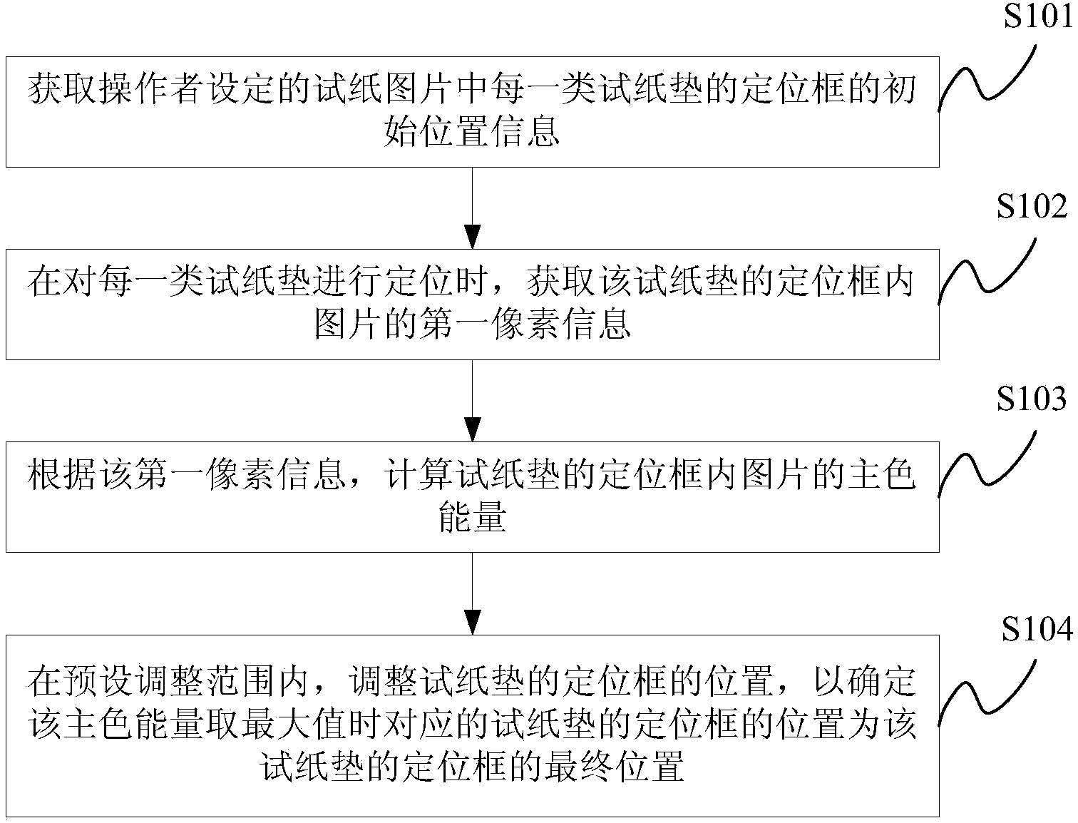
[0074] Such as figure 1 Shown is a flow chart of a test paper positioning method of the present invention, the method may include the following steps:
[0075] Step S101: Obtain the initial position information of the positioning frame of each type of test paper pad in the test paper picture set by the operator.
[0076] Wherein, the initial position information of the positioning frame may include: the length and width of the positioning frame of each type of test paper pad, and the initial coordinate value of the first vertex. Preferably, the first vertex may be the vertex of the lower left corner of the positioning frame.
[0077] In the embodiment of the present invention, since the test strip is only a part of the input picture, it needs to be separated from the input picture, and then each type of test paper pad can be separated from the test strip. For this process, the initial positioning of the test strip of the input image can be obtained by relying on the observat...
Embodiment 2
[0106] Such as Figure 4 Shown is a flow chart of another test paper positioning method of the present invention, which method may include:
[0107] Step S401: Obtain the initial position information of the positioning frame of each type of test paper pad in the test paper picture set by the operator.
[0108] Wherein, the acquired initial position information of the positioning frame includes: the length and width of the positioning frame of each type of test paper pad, and the initial coordinate value of the first vertex.
[0109] In the embodiment of the present invention, the operator can directly use the mouse to mark the initial position of the positioning frame of each type of test paper pad in the input test paper picture. Of course, before step S401 is performed, the operator can also initially position the test paper pad, that is, use the mouse to initially calibrate the coordinate values of the four vertices of the test paper picture in the input test paper pictu...
Embodiment 3
[0150] Such as Figure 7 As shown, it is a structural schematic diagram of a test paper positioning system of the present invention, and the system may include:
[0151] The first obtaining module S701 is used to obtain the initial position information of the positioning frame of each type of test paper pad in the test paper picture set by the operator.
[0152] Wherein, the acquired initial position information of the positioning frame includes: the length and width of the positioning frame of each type of test paper pad, and the initial coordinate value of the first vertex.
[0153] As another embodiment of the present invention, the operator can first set the coordinates of the four vertices of the test strip picture in the input test strip picture, and then calibrate the initial positions of various test paper pads on the test strip picture. Therefore, The first obtaining module is also used to obtain the coordinate values of the four vertices of the test strip picture ...
PUM
 Abstract
Description
Claims
Application Information
 - R&D
- Intellectual Property
- Life Sciences
- Materials
- Tech Scout
- Unparalleled Data Quality
- Higher Quality Content
- 60% Fewer Hallucinations
Browse by: Latest US Patents, China's latest patents, Technical Efficacy Thesaurus, Application Domain, Technology Topic, Popular Technical Reports.
© 2025 PatSnap. All rights reserved.Legal|Privacy policy|Modern Slavery Act Transparency Statement|Sitemap|About US| Contact US: help@patsnap.com