Sample transfer device

A push device and sample transfer technology, applied in the direction of transportation, packaging, conveyors, etc., can solve the problems of unfavorable work efficiency, improved workpiece saving, limited advancing distance, workpiece fatigue, etc., to achieve automatic and rapid setting of advancing, improving efficiency and saving cost effect

Active Publication Date: 2016-02-03
SICHUAN ORIENTER BIOLOGICAL TECH
View PDF5 Cites 0 Cited by
  • Summary
  • Abstract
  • Description
  • Claims
  • Application Information

AI Technical Summary

Problems solved by technology

[0002] The existing driving components are all cycled by a single circuit to complete the propulsion work, but this single circuit cycle is easy to cause fatigue of the workpiece because the circuit is short and straight, and the advancing distance is limited, which is not conducive to the improvement of work efficiency and the workpiece savings

Method used


Image

  • Sample transfer device
  • Sample transfer device

Examples


Embodiment 1

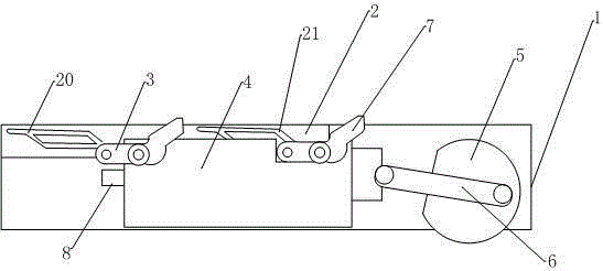
[0019] Such as figure 1 As shown, the sample transfer pushing device includes a mounting bracket 1, a plastic mounting plate A2 is provided above the mounting bracket 1, a linear guide rail 8 is provided below the mounting plate A2, and a linear guide rail 8 that can move back and forth in the horizontal direction is arranged on the linear guide rail 8. The mounting plate B4 made of stainless steel, the left end of the mounting plate B4 is hinged with the spring push block A3, the right end of the mounting plate B4 is hinged with the spring push block B7, and the mounting plate A2 corresponds to the spring push block A3 and the spring push block B7 respectively. The positions are respectively provided with the push route groove A20 and the push route groove B21 for the bullet push block A3 and the spring push block B7 to pass through. Both the push route groove A20 and the push route groove B21 are parallelogram grooves extending from the upper and lower sides. The right side ...

Embodiment 2

[0022] Such as figure 1 and figure 2 As shown, similar to embodiment 1, the difference is:

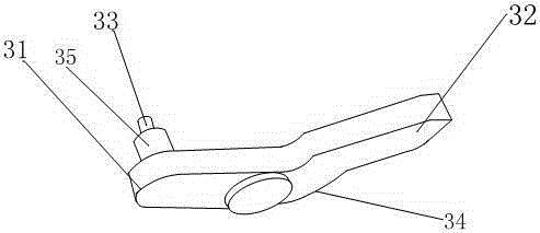
[0023] The elastic push block A3 or the elastic push block B7 includes a sliding plate with a hole, one end of the sliding plate is a U-shaped end 31, and the other end is an inclined end 32 connected with the U-shaped end 31 by an arc section 34, and the arc section 34 The angle is 30-75°, and the setting of the arc section 34 is beneficial to the reciprocating motion of the spring push block A3 and the spring push block B7, and the U-shaped end 31 is also connected with a contact end responsible for sliding in the push route groove A20 or the push route groove B21 33. The cylindrical shape of the contact end 33 facilitates its sliding in the groove. The structure of the spring pushing block A3 and the spring pushing block B7 is conducive to their reciprocating movement driven by the mounting plate B4.

[0024] The width of the pushing path groove A20 matches the end of the conta...


PUM


Abstract

The invention discloses a sample movement pushing device. An installation plate A is arranged on the top of an installation support, a linear guide rail and an installation plate B are arranged below the installation plate A, the installation plate B is arranged on the linear guide rail and can move in a front-and-rear mode in the horizontal direction, an elastic pushing block A is hinged to the left end of the installation plate B, an elastic pushing block B is hinged to the right end of the installation plate B, a pushing path groove A and a pushing path groove B are formed in the installation plate A, and correspond to the elastic pushing block A and the elastic pushing block B in position respectively, the elastic pushing block A and the elastic pushing block B can pass through the pushing path groove A and the pushing path groove B respectively, the pushing path groove A and the pushing path groove B are parallelogram grooves, and the upper edge and the lower edge of each parallelogram groove extend out. The sample movement pushing device is simple and rapid, pushing can be set automatically and rapidly, the pushing path is a quadrangular closed path, the downwards-advancing and upwards-withdrawing passing mode can be adopted for the elastic pushing blocks, mechanical fatigue caused by existing linear reciprocating motion to elastic pushing blocks is avoided, and the pushing distance is increased, so that the sample movement pushing device is more durable, the cost is reduced, and efficiency is improved.

Description

technical field [0001] The present invention relates to the field of biomechanics, in particular, to a sample transfer pushing device. Background technique [0002] Existing driving components are all based on a single circuit cycle to complete the propulsion work, but this single circuit cycle method is easy to cause workpiece fatigue because the circuit is short and straight, and the advancing distance is limited, which is not conducive to the improvement of work efficiency and the workpiece savings. Contents of the invention [0003] In order to solve the above problems, the present invention provides a sample transfer pushing device. The push block provided by the push device can perform a cyclical reciprocating movement of "downward, upward, and backward" along a quadrilateral closed circuit, reducing the mechanical fatigue of the push block. And wear degree, increase the propulsion distance, improve work efficiency and precision. [0004] The technical solution ado...

Claims


Application Information

Patent Timeline
Patent Type & Authority Patents(China)
IPC IPC(8): B65G25/08
Inventor 杨龙贤
Owner SICHUAN ORIENTER BIOLOGICAL TECH
Why Eureka
Try Eureka