A material distribution mechanism of an injection molding product feeder

A technology of injection molding products and material distribution mechanism, which is applied in the direction of conveyors, transportation and packaging, etc., can solve the problems of no solution, inability to use valve blanking and material distribution mechanism, and inability to copy and copy sleeves, etc., to achieve the goal of improving material distribution efficiency Effect

Inactive Publication Date: 2016-05-18
昕迪智能装备(东莞)有限公司
View PDF7 Cites 0 Cited by
  • Summary
  • Abstract
  • Description
  • Claims
  • Application Information

AI Technical Summary

Problems solved by technology

How to efficiently distribute the injection molding products taken out of the receiving mechanism to the subsequent conveying mechanism one by one, there are many material distributing mechanisms in the large field of automatic equipment transportation, but these mechanisms are all adapted to different working conditions , Different products are specially designed, with strong working conditions and product pertinence
For example, the patent No. 201320215456.0 discloses a valve blanking and distributing mechanism. This mechanism is mainly used for collecting and distributing materials after valve processing. This mechanism has a simple structure and adopts a chain rotating device, and the efficiency is also high, but it cannot be copied. Or just make appropriate improvements and apply it to the material distribution of injection molding products in this field: 1. The material properties of injection molding products are different from those of metal valves, and the valve blanking and distribution mechanism cannot be used for material distribution. The working condition of the valve is different from the working condition before and after valve material distribution, so it cannot be copied and used
There is no suitable solution in this field yet

Method used


Image

  • A material distribution mechanism of an injection molding product feeder
  • A material distribution mechanism of an injection molding product feeder
  • A material distribution mechanism of an injection molding product feeder

Examples


Embodiment Construction

[0030] The present invention will be further described below in conjunction with drawings and embodiments.

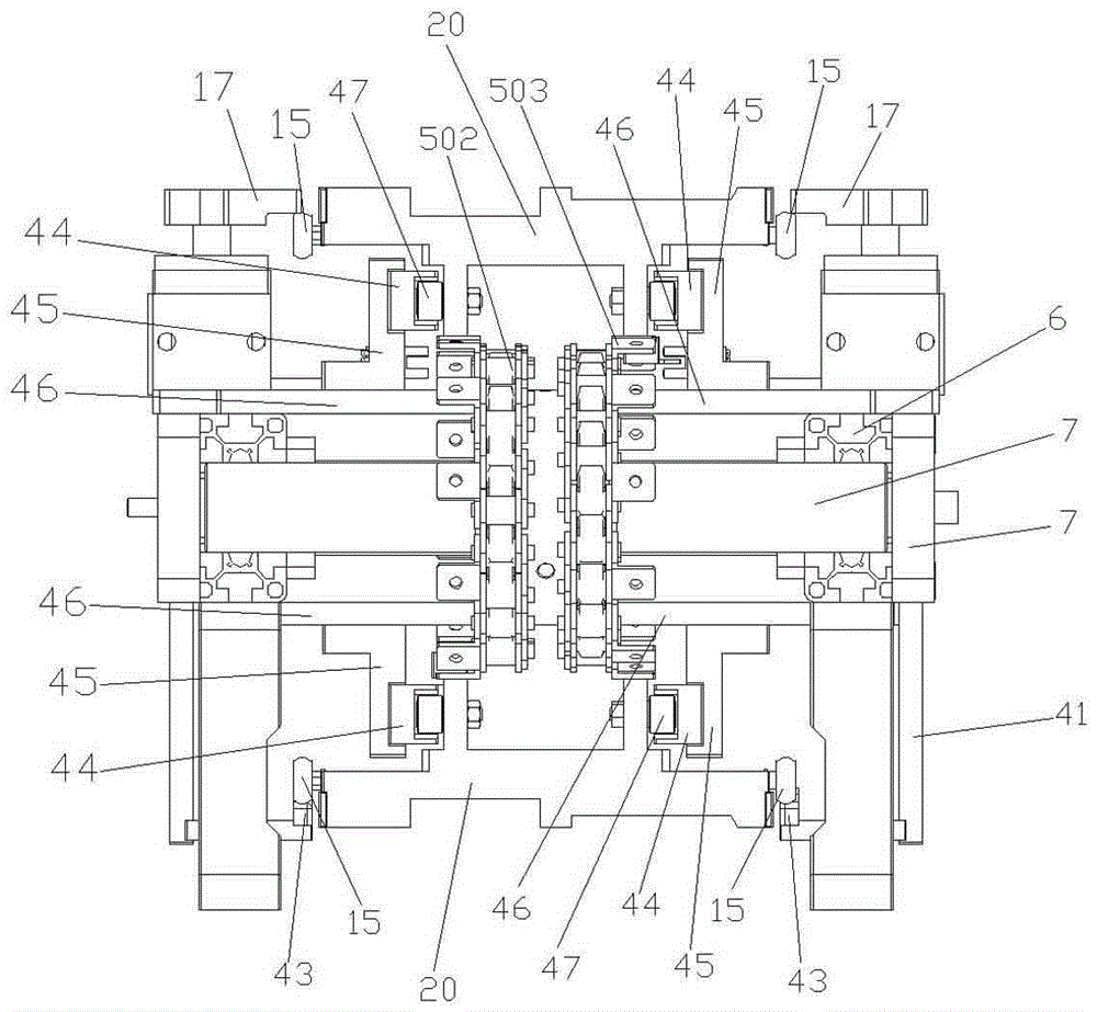
[0031] like Figure 4 As shown, the cross-section of the support rod 6 is a square, and there are installation grooves on the four sides. Two vertical and two horizontal support columns 7 form a frame-shaped structure. There are four fixed plates 8 with shaft holes 801 on them, which are fixedly installed on the two ends of the support rod 6 respectively; On the surface, there are four supporting feet 9.

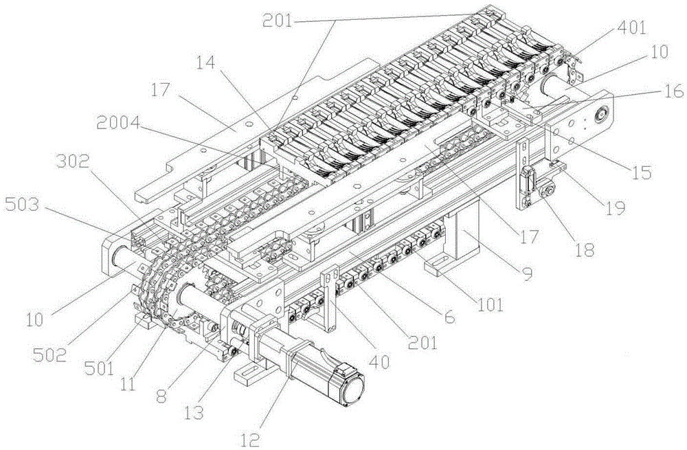
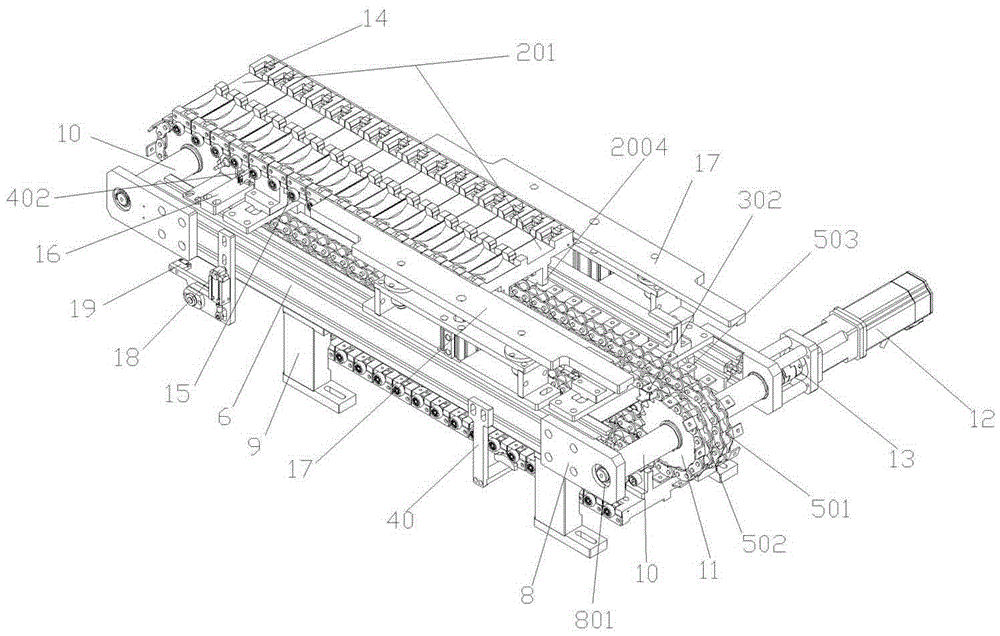
[0032] like figure 1 , 2 , 5, there are two rotating shafts 10, which are respectively installed in the shaft hole 801 of the fixed plate 8 at the two ends of the support rod 6, and the sprocket wheel 11 is a single double row sprocket wheel, and there are two, which are respectively installed on the rotating shaft 10, There are two chains, arranged in parallel on the left and right, the first chain 501 on the right, and the second chain 502 on the left. Both chai...


PUM


Abstract

The invention relates to a distribution mechanism of a feeding machine, in particular to a distribution mechanism of a feeding machine of plastic injection molding products. The distribution mechanism of the feeding machine of the plastic injection molding products is composed of two same transfer mechanisms, each transfer mechanism comprises a support, a chain transfer device, product fixing devices, a sensing device, charging control devices and discharging control devices; the product fixing devices can be gathered together for receiving and can also be independently separated for discharging, the two transfer mechanisms and the two sets of product fixing devices on each transfer mechanism can be used for alternately receiving and distributing materials under reciprocating and continuous rotation of the chain transfer devices, distribution efficiency of the distribution mechanism is improved obviously, and distribution of the materials in a conveying process of the plastic injection molding products is achieved.

Description

technical field [0001] The invention relates to a material distribution mechanism of a feeder, in particular to a material distribution mechanism of an injection molding product feeder. Background technique [0002] Injection molding of plastic products often requires a large number of products to be molded at one time, especially for small plastic products, the number of molds at one time is often more. After the injection molding is completed, there needs to be a process of mold release, sorting, and transportation before packaging or other processes. The traditional manual operation method is that workers directly pick from the mold, and then collect, organize, and transport, which is inefficient. Later, there was an automated manipulator. Through its reclaiming device, the injection molding product can be directly taken out of the mold and placed on the receiving mechanism. The products stored on the receiving mechanism are arranged in the same way as they are in the mo...

Claims


Application Information

Patent Timeline
Patent Type & Authority Patents(China)
IPC IPC(8): B65G17/46B65G17/12
Inventor 梁启明
Owner 昕迪智能装备(东莞)有限公司
Why Eureka
Try Eureka