Rotary and rapid positioning device
A positioning device and fast technology, applied in positioning devices, precision positioning equipment, clamping, etc., can solve the problems of poor positioning accuracy of parts, inability to achieve high precision, low production efficiency, etc., achieve low manufacturing cost and facilitate large-scale investment Use, high usability effect
- Summary
- Abstract
- Description
- Claims
- Application Information
AI Technical Summary
Problems solved by technology
Method used
Image
Examples
Embodiment 1
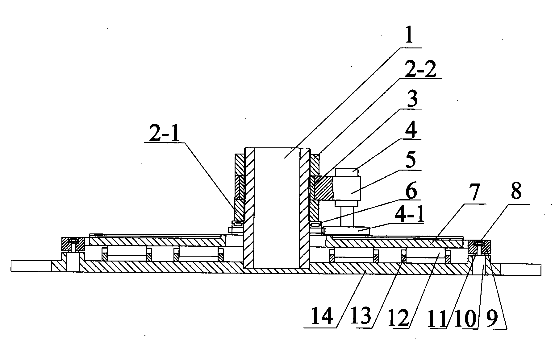
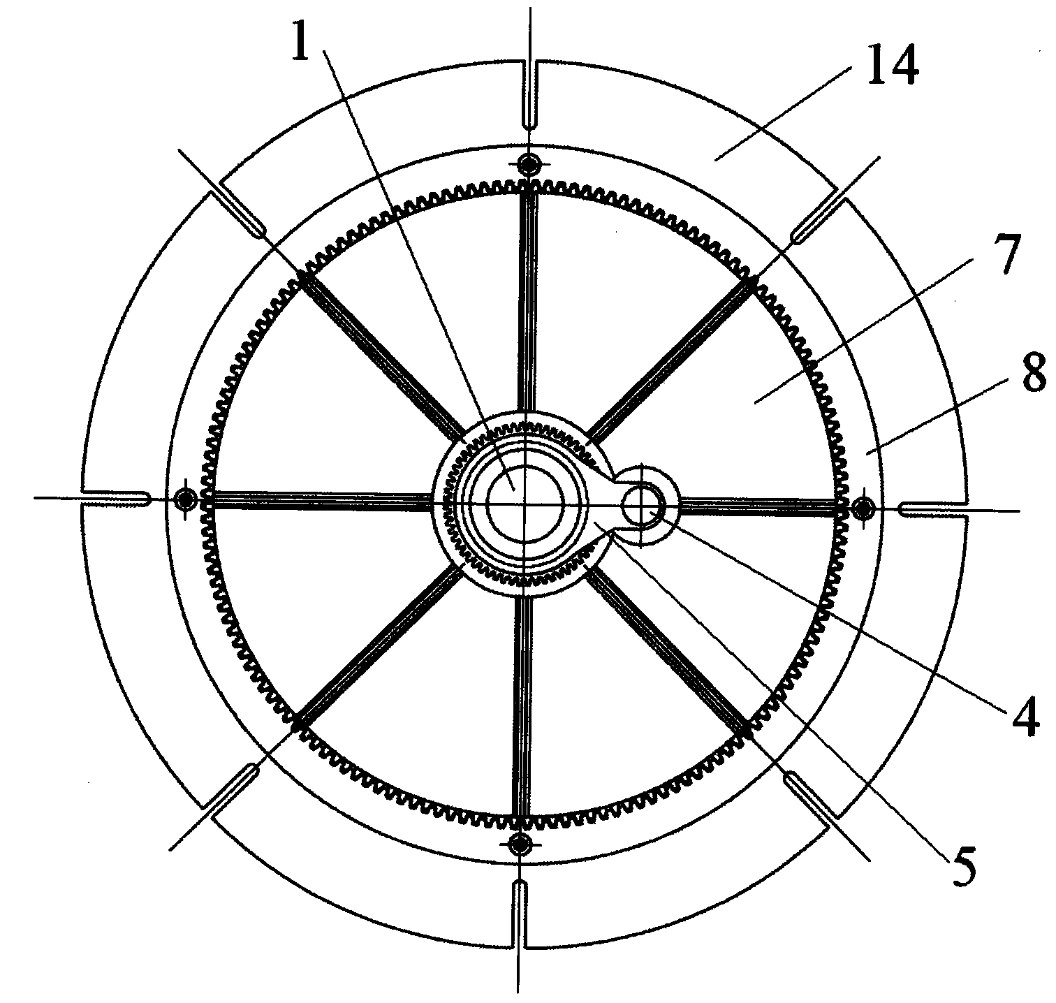
[0025] In the present invention, when the electric transmission mechanism is not installed, the positioning mandrel 1 is installed in the center of the base 14, and the positioning mandrel 1 is covered with a swivel 7, such as Figure 7 , Figure 8 As shown, the small gear ring 7-1 of the swivel 7 passes through the needle bearing 6 (as Figure 5 shown) is connected with the lower pressure ring 2-1, the needle roller bearing 6 is sleeved on the positioning mandrel 1, and the top of the needle roller bearing 6 is fixed with the lower pressure ring 2-1. The large gear ring 7-2 of the swivel 7 is in contact with the needle roller 12, the needle roller 12 is installed on the base 14 through the support block 13, the bottom of the hydraulic jack 10 is installed in the base 14, and the positioning gear ring 9 has a stepped hole. The support rod in the jack 10 is installed in the positioning gear ring 9 step holes, and the two ends are fixed with bottom ring 11 and nut 8 . The top ...
Embodiment 2
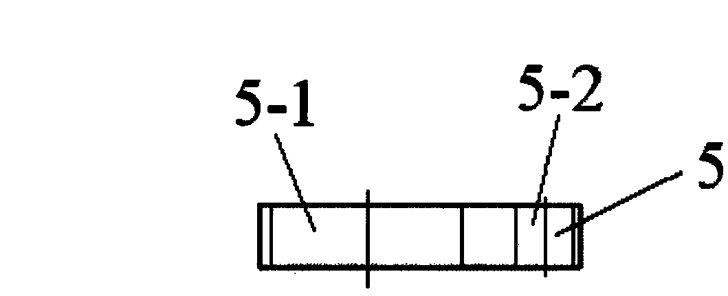
[0034] When the present invention installs the electric transmission mechanism additionally, its structure increases the electric transmission mechanism on the basis of embodiment 1. The lower pressure ring 2-1 is connected with the upper pressure ring 2-2 through an electric transmission mechanism, and the electric transmission mechanism includes clamping blocks 5, such as image 3 , Figure 4 As shown, there is a positioning mandrel 1 in the large hole 5-1 of the clamping block 5, and the clamping block 5 and the positioning mandrel 1 are connected by a lining ring 3, and there is sliding friction contact between them. The top is fixed with the upper pressure ring 2-2. The motor 4 is installed in the small hole 5-2 of the clamping block 5, and the transmission gear 4-1 at the bottom of the motor 4 is meshed with the small gear ring 7-1 of the swivel 7.
[0035] The operation and use steps of a rotating quick positioning device are as follows:
[0036] 1. The parts in the ...
PUM
 Abstract
Description
Claims
Application Information
 - R&D
- Intellectual Property
- Life Sciences
- Materials
- Tech Scout
- Unparalleled Data Quality
- Higher Quality Content
- 60% Fewer Hallucinations
Browse by: Latest US Patents, China's latest patents, Technical Efficacy Thesaurus, Application Domain, Technology Topic, Popular Technical Reports.
© 2025 PatSnap. All rights reserved.Legal|Privacy policy|Modern Slavery Act Transparency Statement|Sitemap|About US| Contact US: help@patsnap.com


