Eureka AIR delivers breakthrough ideas for toughest innovation challenges, trusted by R&D personnel around the world.

Hub for torque transmission

A technology of hubs and meshing parts, applied in clutches, mechanical drive clutches, mechanical equipment, etc., can solve problems such as uneven load distribution

Inactive Publication Date: 2014-06-25
SCHAEFFLER TECH AG & CO KG
View PDF8 Cites 4 Cited by
  • Summary
  • Abstract
  • Description
  • Claims
  • Application Information

AI Technical Summary

Problems solved by technology

However, in principle the problem of uneven load distribution between the teeth still exists and only one tooth is shifted

Method used


Image

  • Hub for torque transmission
  • Hub for torque transmission
  • Hub for torque transmission

Examples


Embodiment Construction

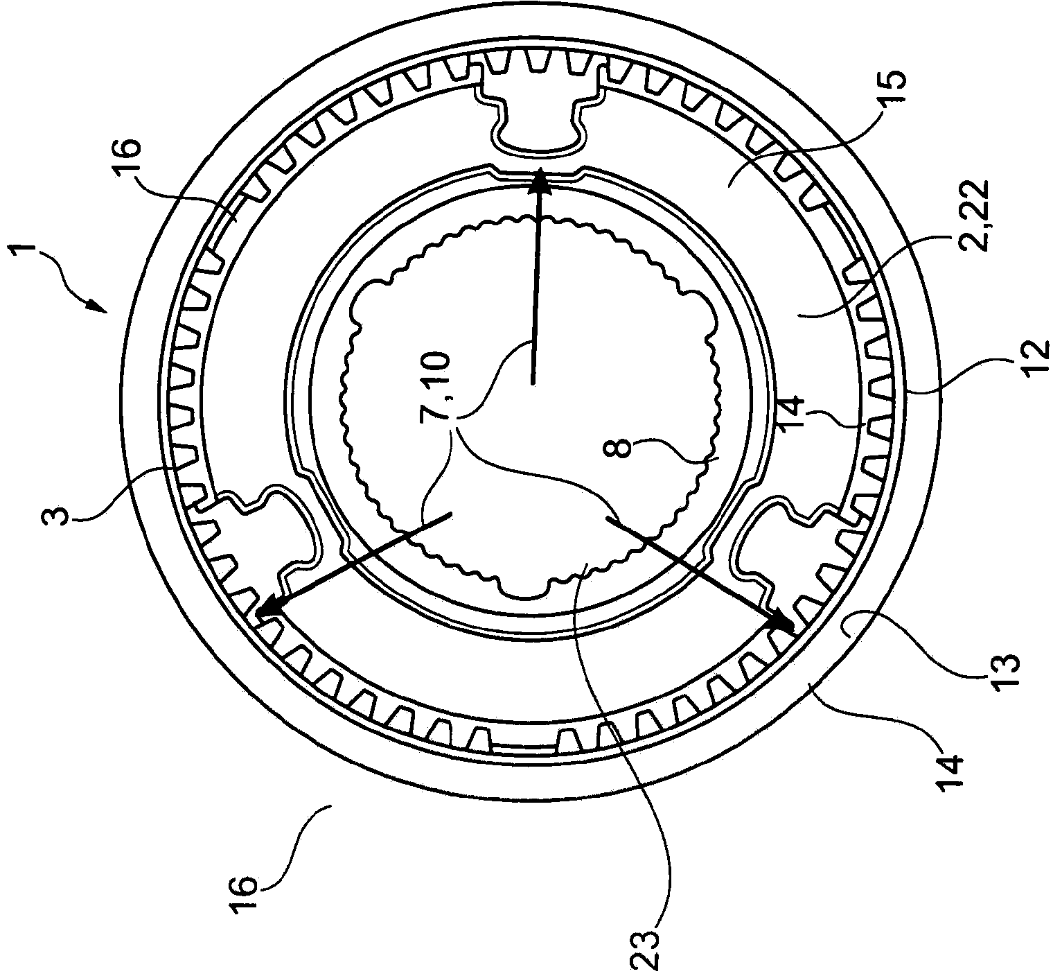
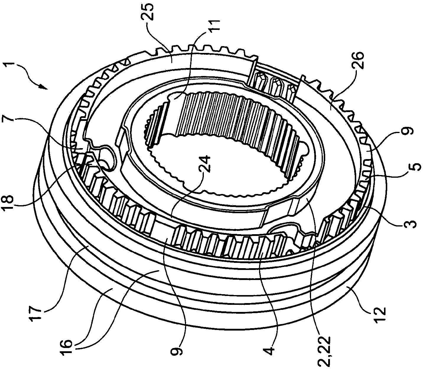
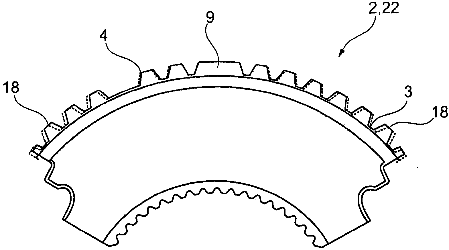
[0033] figure 1 and figure 2 A hub 22 according to the invention is shown as synchronization carrier 2 of the synchronization unit 1 . The hub 22 has an outer toothing 4 on its outwardly directed surface 3 . Concentrically to the outer toothing 4 , the hub has a central recess 23 , by means of which the hub can be fixed in a rotationally fixed manner. For this purpose, the hub 22 has a shaft engagement 8 in the central recess 23 , by means of which the hub can engage into a corresponding engagement of a drive shaft, not shown.

[0034] The hub 22 configured as the synchronization carrier 2 engages with the outer toothing 4 in a complementary inner toothing 14 which concentrically surrounds the inwardly directed sliding sleeve 12 of the synchronization carrier 2 as the second component. Arranged on the surface 13 . The sliding sleeve 12 has on the outside a shift fork groove 17 formed by an annular rim 16 for engaging a shift fork (not shown) of the actuating synchronizati...


PUM


Abstract

A hub (2, 22) having an external toothing (4) for engaging into a sleeve internal toothing and having a central recess (23) for making contact with a shaft, wherein the external toothing (4) is formed from a plurality of toothing portions which are separated from one another by toothing windows (7), and wherein the hub (2, 22), when not mounted on the shaft, has a pitch error which decreases in a direction away from the toothing windows (7).

Description

technical field [0001] The invention relates to a wheel hub with an outer toothing for engagement into an inner toothing of a bushing and a central recess for contact with a shaft, wherein the outer toothing is formed by a plurality of toothing segments, which are separated from each other by an engagement portion opening. Background technique [0002] Hubs of this type are known in the art in a wide variety of applications, for example as transmission gears. The toothing of the hub has toothing sections in which the teeth are spaced equidistantly from one another. In addition, there are areas in which the toothing is interrupted, for example by recesses for the presynchronizing element, or individual teeth are wider, which engage in correspondingly wider tooth grooves in the corresponding toothing, so that The components that engage with each other can be correctly positioned relative to each other. [0003] A sleeve-shaped sliding sleeve is known from DE 38 17 767 A1, w...

Claims


Application Information

Patent Timeline
IPC IPC(8): F16D23/06
CPCF16D23/06F16D2023/0637F16D2023/0656
Inventor 亚历克斯·尼古拉斯奎克福尔克哈德·瓦尔特鲁道夫·弗尔克
Owner SCHAEFFLER TECH AG & CO KG
Why Eureka
Eureka Blog
Learn More