
Multi-component composite energy storage system grid combination control method based on power prediction

A multi-component composite and control method technology, applied in energy storage, AC network load balancing, single-network parallel feeding arrangement, etc., can solve problems such as low energy density, unsuitable for frequent charging and discharging, and short charging time

Active Publication Date: 2014-06-25
STATE GRID CORP OF CHINA +2
View PDF6 Cites 19 Cited by
  • Summary
  • Abstract
  • Description
  • Claims
  • Application Information

AI Technical Summary

Problems solved by technology

[0002] At present, the development and application of microgrid control strategies are still immature, and further improvement and exploration are needed. At this stage, the main equipment for energy storage for microgrid grid connection is supercapacitors and batteries; supercapacitors have high power density and long cycle life. long, short charging time, high reliability, and low energy density, while the battery has a high energy density and can store energy in large capacity, but it is not suitable for frequent charging and discharging. By combining the advantages of these two energy storage devices, there is no combined application

Method used


Image

  • Multi-component composite energy storage system grid combination control method based on power prediction
  • Multi-component composite energy storage system grid combination control method based on power prediction
  • Multi-component composite energy storage system grid combination control method based on power prediction

Examples


Embodiment Construction

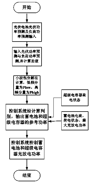
[0045] Attached below Figure 1~8 The present invention is further described with embodiment:

[0046] The structure principle of the microgrid control system is as follows: Figure 4 As shown, the storage battery, supercapacitor and photovoltaic battery module are connected to the grid bus through AC / DC, and the load is directly connected to the grid bus. The control system uses data collection to obtain the following: Figure 2~3 The input voltage value U and current value I are output by the control system to control AC / DC corresponding to the storage battery, supercapacitor and photovoltaic cell assembly, and the output of the control system also controls the change of the load.

[0047] Depend on Figure 1~8 As can be seen from the shown embodiment, the main steps of this embodiment are as follows:

[0048] Step 1: According to Figure 6~8 Prediction of photovoltaic output power of medium photovoltaic cell modules and load power prediction , to calculate the diffe...


PUM


Abstract

The invention discloses a multi-component composite energy storage system grid combination control method based on power prediction, comprising steps of calculating difference value PV-L of the photovoltaic output power prediction value PV and the load power prediction value PL according to the photovoltaic output power prediction value PV and the load power prediction value PL and, utilizing a wavelet packet composition method to map PV-L to the subspaces of m wavelet packets to obtain signals with different frequencies, using the frequency signals which are close to the responding frequency of a storage battery in the frequency signals as low frequency signals P low which are complimented by the storage battery and using the rest of the frequency signals and the frequency signals which are not absorbed by the battery as high frequency signals P high which are complimented by a super capacitor, using an external loop control method and an inner loop current control method to output the real power of the storage battery and the super capacitor and control the charging and discharging power of the storage battery and the super capacitor by utilizing the state of charges of the super capacitor and the current, the state of charge and maximum charge-discharge power of the storage battery according to the real condition. The advantages of the invention are safe, stable, and economic in operation. Furthermore, the times of charging and discharging of the storage battery are reduced.

Description

technical field [0001] The invention relates to a grid-connected control method of a multivariate composite energy storage system based on power prediction, which belongs to the technical fields of distributed power generation, energy storage, power prediction, wavelet analysis, photovoltaic power generation, microgrid and new energy power generation, and is suitable for multivariate composite energy storage systems. Control strategies for energy storage systems. Background technique [0002] At present, the development and application of microgrid control strategies are still immature, and further improvement and exploration are needed. At present, the main equipment for energy storage for microgrid grid connection is supercapacitors and batteries; supercapacitors have high power density and long cycle life. long, short charging time, high reliability, and low energy density, while the battery has a high energy density and can store energy in large capacity, but it is not s...

Claims


Application Information

Patent Timeline
IPC IPC(8): H02J3/38H02J3/28
CPCY02E10/56Y02E70/30
Inventor 高志强褚华宇范辉孟良孙中记梁宾杨潇
Owner STATE GRID CORP OF CHINA
Learn More