Connector

A technology of connectors and housings, which is applied in the direction of connections, components of connection devices, electrical components, etc., and can solve problems such as the inability to omit the anti-off structure, the large gap, and the increase in the width of the locking arm.

Inactive Publication Date: 2014-06-25
SUMITOMO WIRING SYST LTD
View PDF12 Cites 5 Cited by
  • Summary
  • Abstract
  • Description
  • Claims
  • Application Information

AI Technical Summary

Problems solved by technology

[0008] However, in the case of the conventional connector described above, the locking claws protrude outside the widthwise ends of the front end of the arm body, and the widthwise end portions of the slider are positioned to cover the arm body. Increased width dimension on the front end side of the lock arm
[0009] On the other hand, in the state where the housing and the counterpart housing are fitted, a pair of guide ribs formed on the counterpart housing are located on both sides in the width direction of the housing, across the front end portion of the lock arm, so it is necessary to ensure The gap in the width direction between the two guide ribs is large, so that the width dimension of the opposing housing is also increased
Moreover, when the two housings are fitted together, except for the guide rib, various parts formed in the other housing are located on both sides of the front end of the lock arm in this housing, so there are two housings. The problem that it has to be enlarged due to the width dimension of the front end portion of the lock arm
Even so, it is necessary to restrict the disengagement prevention structure of the slider from the lock arm, and there is a dilemma that the disengagement prevention structure cannot be omitted.

Method used


Image

  • Connector
  • Connector
  • Connector

Examples


Embodiment 1

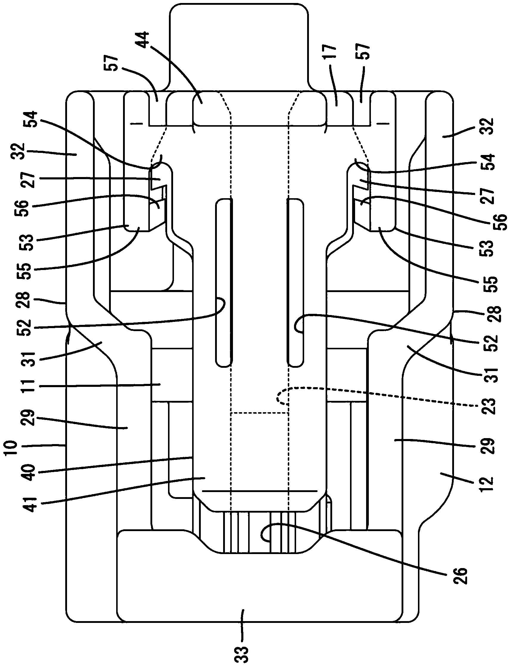
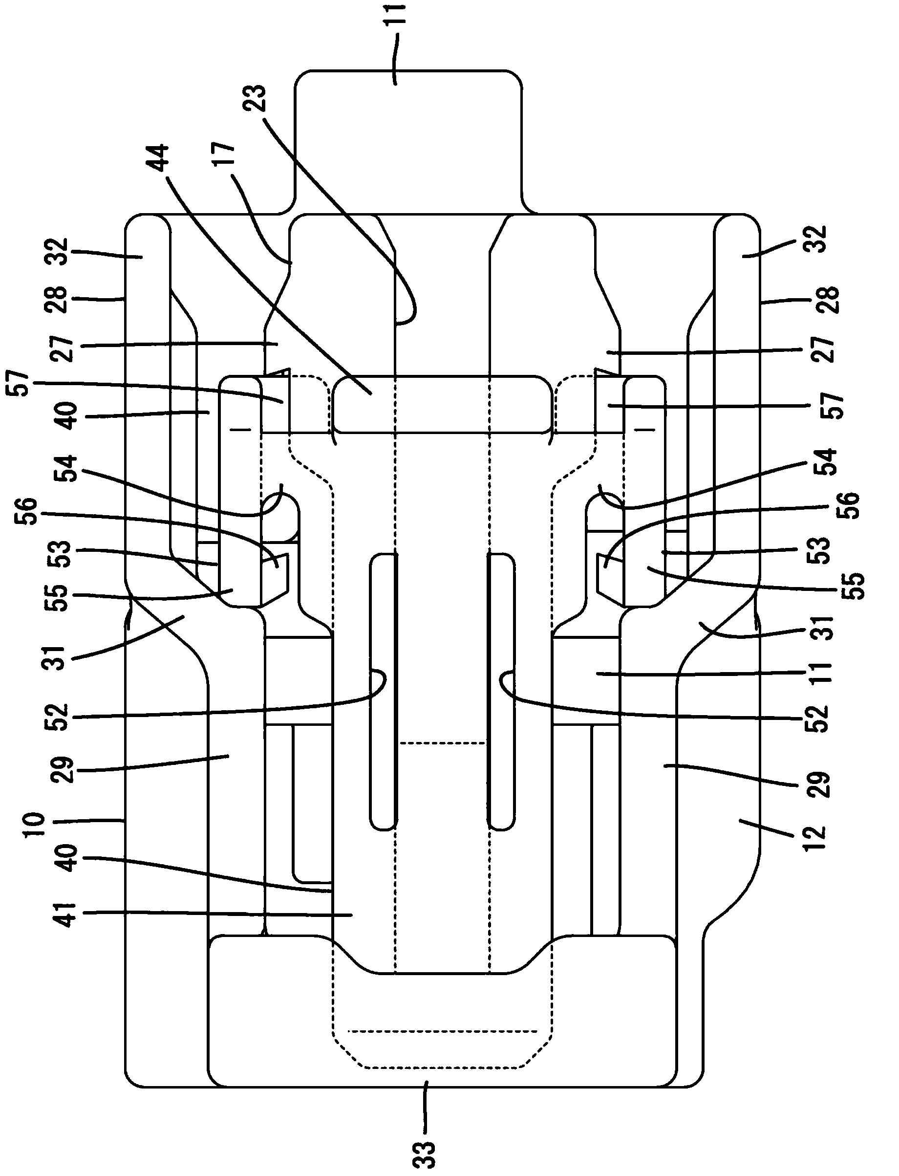
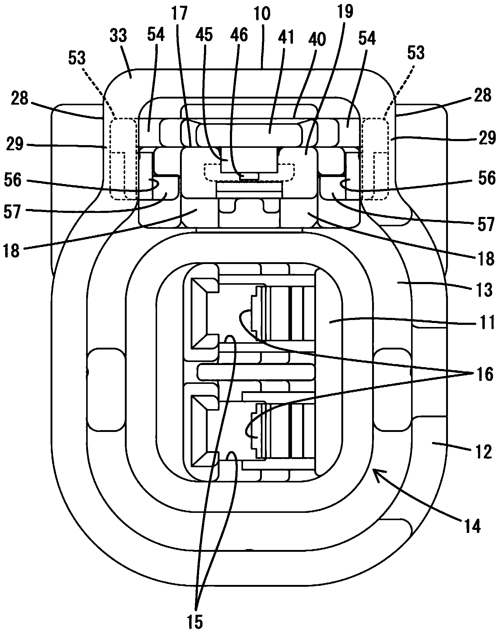
[0032] use Figure 1 to Figure 13 Example 1 of the present invention will be described. The connector of the present embodiment is capable of fitting with a mating housing 100 , and is configured to include a housing 10 , a slider 40 , and a terminal fitting 70 . In addition, in the following description, regarding the front-rear direction, the side of the mating surface with respect to the counterpart housing 100 is defined as the front.

[0033] Such as Figure 5 As shown, the counterpart housing 100 is made of synthetic resin and has a cylindrical cover portion 101 . A locking portion 102 protrudes from the upper surface of the upper wall of the cover portion 101 , and a pair of guide ribs (not shown) protrude from both sides in the width direction of the locking portion 102 . The two guide ribs are formed to extend substantially parallel to each other in the front-rear direction. Furthermore, the male protruding piece 201 of the mating terminal fitting 200 is protrudin...


PUM


Abstract

The invention provides a connector, wherein the miniaturization requirement of the connector is met based on the anti-falling structure of a sliding part. The sliding part is arranged on a shell and is movable between a backward position and a forward position. The sliding part is composed of a plate-like sliding part main body capable of sliding along the outer surface of an arm main body. The sliding part main body is provided with an outer clamping portion configured to abut against an outer clamping and supporting portion in the tabling direction when the sliding part is at the backward position, so as to limit the sliding part and prevent the sliding part from disengaging from a locking arm backwards, wherein the outer clamping and supporting portion is arranged on the outside of the rear end portion of the arm main body in the width direction. The sliding part main body is also provided with an inner clamping portion. The inner clamping portion is composed of a part positioned on the inner side of the inner clamping portion in the width direction and arranged forwards than the outer clamping portion, and is capable of being abutted against an inner clamping and supporting portion in the thickness direction during movement so as to limit the sliding part and prevent the sliding part from disengaging towards the outer side of the locking arm along the thickness direction, wherein the inner clamping and supporting portion is formed on the inner side of the arm main body in the width direction.

Description

technical field [0001] The invention relates to a connector. Background technique [0002] The connector disclosed in Patent Document 1 includes a housing and a slider as a fitting detection member attached to the housing so as to be movable between a retracted position and an advanced position. The case has a bendable lock arm that maintains a fitted state with the mating case, and the lock arm has a plate-shaped arm body extending in the front-rear direction. Also, the slider has a slider body that slides on the upper surface of the arm body during movement from the retracted position to the advanced position. [0003] A pair of detachment prevention protrusions are formed at the front end of the arm main body, and locking claws are formed at the front end of the slider main body on the front end side of the pair of pressing parts. The two anti-removal protrusions are formed in the form of protruding outward from both ends in the width direction at the front end of the a...

Claims


Application Information

Patent Timeline
Patent Type & Authority Applications(China)
IPC IPC(8): H01R13/639
Inventor 栗泽裕也
Owner SUMITOMO WIRING SYST LTD
Why Eureka
Try Eureka