
Displacement sensor fault detection circuit and control system thereof

A fault detection circuit and displacement sensor technology, applied in the direction of electrical program control, measuring electricity, measuring electrical variables, etc., can solve the problems of inaccurate signals, high cost, short-circuiting the positive pole of the power supply, etc., and achieve the effect of simple circuit and easy implementation

Active Publication Date: 2014-06-25
WUJIANG LYUKONG ELECTRIC CONTROL TECH
View PDF7 Cites 19 Cited by
  • Summary
  • Abstract
  • Description
  • Claims
  • Application Information

AI Technical Summary

Problems solved by technology

[0005] 1. The signal is disconnected;
[0006] 2. The signal is short-circuited, that is, short-circuited to ground or short-circuited to the positive pole of the power supply;
[0007] 3. The power supply of the sensor fails, resulting in inaccurate signals
Although this method can detect the above-mentioned first and second types of faults, it actually uses the principle of probability, that is, it is considered that the probability of failure of two signals at the same time is very low, so 100% accuracy cannot be guaranteed.
At the same time, for the above-mentioned third type of fault, this method cannot effectively detect it, because when the power supply failure of the sensor occurs, the functional relationship between the two signals may not have a large deviation, but the two signals are wrong
In addition, this method also has the disadvantage of high cost due to the doubling of corresponding components and circuits.

Method used


Image

  • Displacement sensor fault detection circuit and control system thereof

Examples


Embodiment Construction

[0035] In order to make the object, technical solution and advantages of the present invention clearer, the present invention will be further described in detail below in conjunction with the accompanying drawings and embodiments. It should be understood that the specific embodiments described here are only used to explain the present invention, not to limit the present invention.

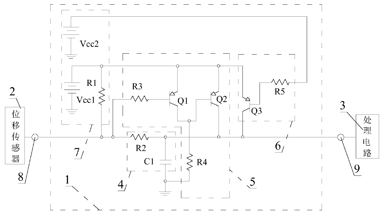
[0036] see figure 1, The displacement sensor fault detection circuit 1 provided by the preferred embodiment of the present invention is applied in a control system for quickly detecting the output signal of the displacement sensor 2 , and the control system further includes a processing circuit 3 . The processing circuit 3 quickly judges three types of faults of the displacement sensor 2, namely short circuit fault, open circuit fault and power supply failure fault, according to the detection signal of the displacement sensor fault detection circuit 1 . In this embodiment, the processing circuit 3...


PUM


Abstract

The invention discloses a displacement sensor fault detection circuit and a control system thereof. The displacement sensor fault detection circuit comprises a power circuit, a short-circuit fault detection circuit, an open-circuit fault detection circuit and a power supply failure fault detection circuit, and further comprises a power supply Vcc1, a power supply Vcc2, a resistor R1, a resistor R3, a resistor R4, a resistor R5, a transistor Q1, a transistor Q2 and a transistor Q3. The input end of the short-circuit fault detection circuit is the signal input end of the displacement sensor fault detection circuit and is grounded through the R1 and the Vcc1, and the output end of the short-circuit fault detection circuit is the signal output end of the displacement sensor fault detection circuit. The base electrode of the Q1 is connected to the signal input end through the R3, the emitting electrode of the Q1 is connected to the positive electrode of the Vcc1, and the collector electrode of the Q1 is grounded through the R4. The base electrode of the Q2 is connected with the collector electrode of the Q1, the emitting electrode of the Q2 is connected to the positive electrode of the Vcc1, and the collector electrode of the Q2 is connected to the signal output end. The emitting electrode of the Q3 is connected with the positive electrode of the Vcc1, the collector electrode of the Q3 is connected with the signal output end, and the base electrode of the Q3 is connected with the positive electrode of the Vcc2 through the resistor R5.

Description

technical field [0001] The invention relates to a detection circuit and a control system installed with the detection circuit, in particular to a displacement sensor fault detection circuit and a control system equipped with the displacement sensor fault detection circuit. Background technique [0002] A displacement sensor is a linear device used to sense the positional movement of a mechanical object (including linear motion and rotation) and convert it into an electrical signal output. It is widely used in industrial automatic machinery and vehicle automatic actuators, such as on the accelerator pedal. It is used to reflect the change of the pedal position, and it is used on the automatic clutch actuator to reflect the change of the clutch engagement and disengagement position, etc. In these automatic controls, displacement is a very important feedback quantity, which directly affects the control quality and system safety. The displacement sensor is an electronic device,...

Claims


Application Information

Patent Timeline
IPC IPC(8): G01B7/02G01R31/00G01R31/02G05B19/04
Inventor 李磊黄全安
Owner WUJIANG LYUKONG ELECTRIC CONTROL TECH
Learn More