
Solar heater

A technology of solar energy and heaters, which is applied in the direction of solar collectors, solar heating systems, solar thermal energy, etc., can solve the problems of inconvenient use and large volume of solar water heaters, and achieve the effects of convenient use, simplified structure, and satisfactory use requirements

Inactive Publication Date: 2014-06-25
王斌
View PDF5 Cites 1 Cited by
  • Summary
  • Abstract
  • Description
  • Claims
  • Application Information

AI Technical Summary

Problems solved by technology

[0003] The purpose of the present invention is to overcome the defects of large volume and inconvenient use of solar water heaters with water tanks, and propose a new type of solar heater, which simplifies the structure of solar heaters, does not need a water tank, occupies less space, and is easy to use and installation, and make full use of the heat of the sun to achieve the purpose of energy saving

Method used


Image

  • Solar heater
  • Solar heater
  • Solar heater

Examples


Embodiment 1

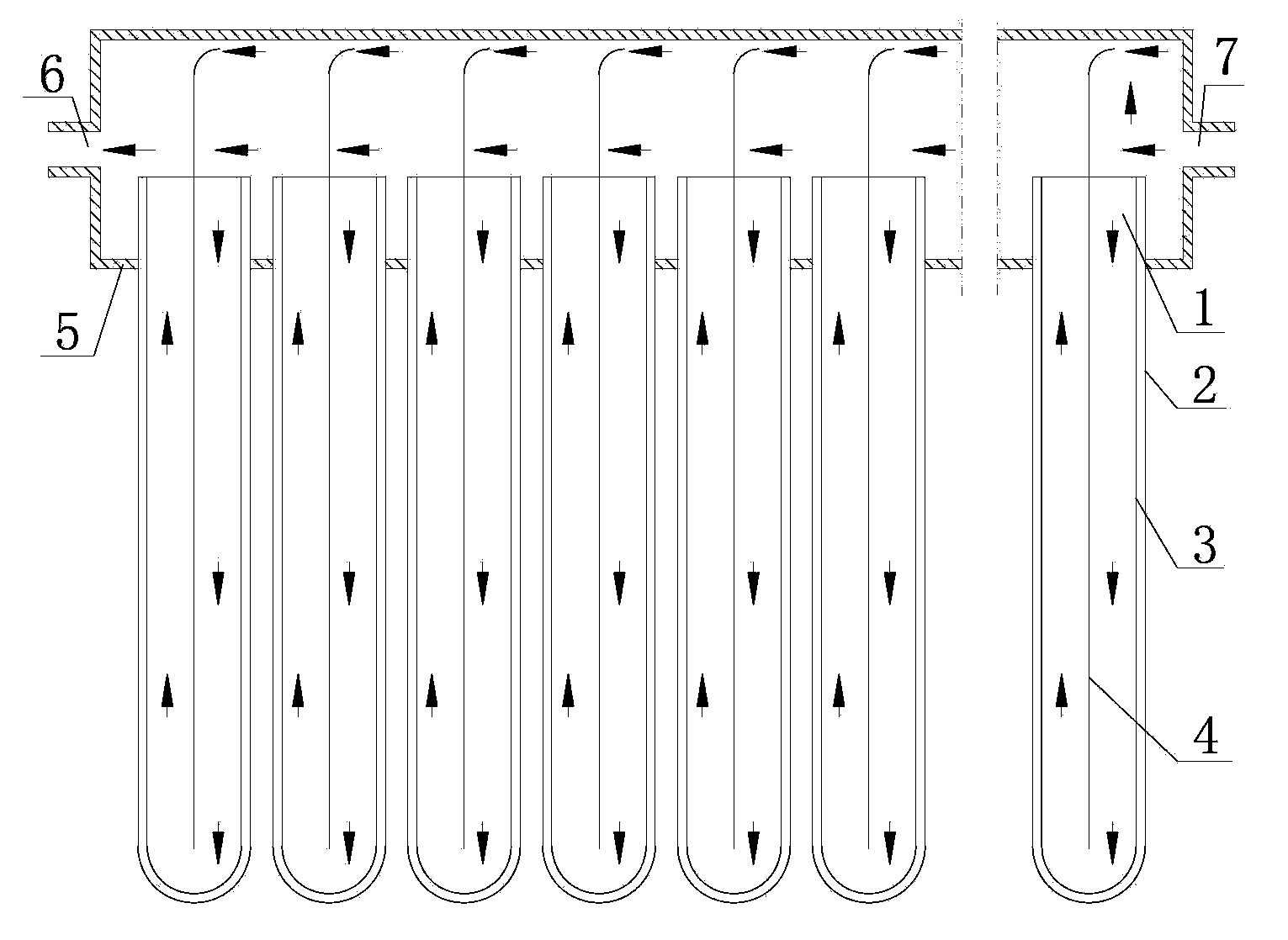
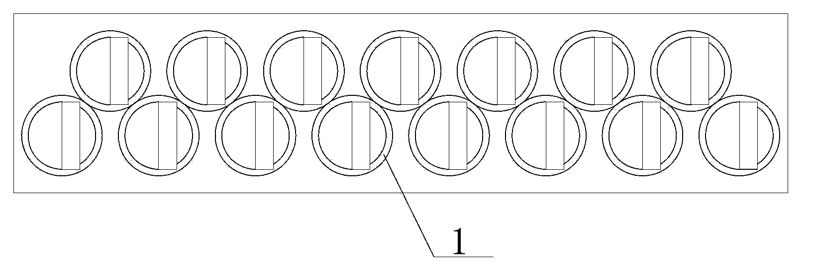
[0014] Such as figure 1 Shown, this solar heater comprises solar tube 1 and the sealing box 5 that connects each solar tube, and wherein between each solar tube 1 is mutually arranged in parallel, and sealing box 5 is arranged on the top of each solar tube 1, and solar tube 1 and The sealing boxes 5 are closed and connected, and the nozzles of the solar tubes 1 are arranged in the sealing boxes 5 and communicate with each other. Such as figure 2 As shown, a row of solar tubes is arranged along the length direction of the sealed box 5 , and there is a certain gap between adjacent solar tubes 1 . The left and right sides of the sealed box 5 are respectively provided with an outlet 6 and an inlet 7 . The heater selects air as the heating medium, so the air inlet 7 is connected with the blower. Each solar tube 1 includes an inner tube 3 and an outer tube 2. There is a vacuum between the inner tube and the outer tube. The outer wall of the inner tube 3 is coated with a solar ab...

Embodiment 2

[0018] In order to fully utilize the solar heat per unit area, the gap between the solar tubes must be fully utilized, so if image 3 As shown, two rows of solar tubes are arranged along the length direction of the sealed box, and each row of solar tubes is arranged in a staggered front and rear. At this time, the solar tubes can make full use of the heat of a unit of sunlight and play a role in saving energy. Such as Figure 4 As shown, three rows of solar tubes can also be arranged along the length direction of the sealed box. At this time, each row of solar tubes is also arranged in a staggered manner along the length direction of the sealed box. In addition, more rows of solar tubes can also be arranged.

[0019] Others are the same as embodiment 1.


PUM


Abstract

The invention relates to a heating device, in particular to a solar heater which comprises solar pipes. Each solar pipe comprises an outer pipe and an inner pipe, vacuum is formed between each outer pipe and the corresponding inner pipe, the solar pipes are parallel to one another, a blocking and diversion piece is arranged in the inner pipe of each solar pipe and inserted along the radius direction of the inner pipe, a gap is reserved between the tail end of each blocking and diversion piece and the bottom wall of the inner pipe of the corresponding solar pipe, a lateral side, along the height direction of the corresponding inner pipe, of each blocking and diversion piece and the wall of the inner pipe are in interference fit, the top end of each blocking and diversion piece is bent and higher than a pipe orifice of the corresponding inner pipe, a sealed box is arranged on the upper portions of the solar pipes, the solar pipes which are parallel to one another and the sealed box are in closed connection, a gap is formed between the top end of an aluminum piece and the wall of the sealed box, an inlet and an outlet are arranged at the left end and the right end of the sealing box, and a medium circulating device is arranged at the inlet and / or the outlet. The solar heater does not need a water tank and is small in occupied space and convenient to use and mount, and heat of sunlight is fully utilized, so that energy resources are saved.

Description

technical field [0001] The invention relates to a heating device, especially a solar heater. Background technique [0002] Existing solar heaters are generally called "solar water heaters", which use liquid, namely water, as the heat-conducting medium. The working principle is to use solar tubes to absorb the heat of sunlight, and conduct the heat to the water in the tubes to heat the water. , when the water reaches a certain temperature, it can meet the needs of people's daily life, and it can also be used as a heating system in winter to increase the indoor temperature. However, in order to increase its heating temperature and ensure the normal circulation of water flow, a large amount of water generally needs to be used, so solar water heaters usually have a water tank. However, the solar energy equipped with a water tank has a large volume and takes up a lot of space, which brings inconvenience to the installation and use of the solar energy, and increases the manufactu...

Claims


Application Information

Patent Timeline
Patent Type & Authority Applications(China)
IPC IPC(8): F24J2/05F24J2/24F24J2/46F24S10/40F24S10/70
CPCY02E10/44
Inventor 王斌
Owner 王斌
Learn More