
Multi-shaft filature locking nozzle clamping jaw mechanism

A screw machine and screw technology, used in metal processing, metal processing equipment, manufacturing tools, etc., can solve the problems of pouring and turning over materials, labor-intensive repetitive labor, machine instability, etc., to eliminate material jams and overturning. materials, saving time and labor costs, and the effect of low production costs

Inactive Publication Date: 2014-06-25
KUNSHAN LITE AUTOMATION EQUIP
View PDF0 Cites 1 Cited by
  • Summary
  • Abstract
  • Description
  • Claims
  • Application Information

AI Technical Summary

Problems solved by technology

[0002] With the continuous increase of labor costs and the bottom of profits, enterprises are facing huge challenges, so it is an inevitable trend to realize production automation and unmanned, especially the existing various electronic products and components are widely used Screw connection, which consumes a lot of manpower to do repetitive work, has become the most urgent need to automate this simple and repetitive action. Recognized
[0003] However, when the existing similar equipment on the market is working, the screw clamping mechanism often clamps incorrectly and the positioning is not accurate. After the product is fed, the material is dumped and turned over, which leads to the instability of the machine and the generation of defective products. Bring great hidden dangers and affect production capacity and machine efficiency

Method used


Image

  • Multi-shaft filature locking nozzle clamping jaw mechanism

Examples


Embodiment Construction

[0014] The present invention will be described in further detail below in conjunction with the accompanying drawings and specific embodiments.

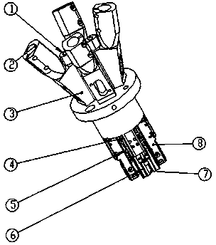
[0015] see figure 1 As shown in the figure, a multi-axis screw machine locking jaw mechanism includes a screwdriver inlet 1, a screw inlet 2, a fixing seat 3, an external force spring 4, a guide shaft 5, a screw positioning member 6, a screw sample 7, and a sliding member 8. A screw inlet 2 is connected next to the screwdriver inlet 1, the lower end of the screw inlet 2 is connected with a fixed seat 3, the lower end of the fixed seat 3 is connected with an external force spring 4, the lower end of the external force spring 4 is connected with a guide shaft 5, and the guide shaft 5 is connected to the lower end of the external force spring 4. The lower end of the shaft 5 is connected with a screw positioning part 6, the screw positioning part 6 is provided with a screw sample 7, the right end of the external force spring 4 is connecte...


PUM


Abstract

The invention discloses a multi-shaft filature locking nozzle clamping jaw mechanism which comprises screwdriver inlets (1), screw inlets (2), a fixed seat (3), an external force spring (4), a guiding shaft (5), a screw positioning piece (6), a screw sample (7) and a sliding piece (8). The multi-shaft filature locking nozzle clamping jaw mechanism is characterized in that the screw inlets (2) are connected beside the screwdriver inlets (1), the lower ends of the screw inlets (2) are connected with the fixed seat (3), the lower end of the fixed seat (3) is connected with the external force spring (4), the lower end of the external force spring (4) is connected with the guiding shaft (5), the lower end of the guiding shaft (5) is connected with the screw positioning piece (6), the screw positioning piece (6) is provided with the screw sample (7), and the right end of the external force spring (4) is connected with the sliding piece (8). According to the multi-shaft filature locking nozzle clamping jaw mechanism, a dispersing mechanism is positioned towards the center through the guiding shaft and spring force so as to be correctly positioned, and it is guaranteed that excursion and dislocation abnormity cannot happen in the screw locking process. The multi-shaft filature locking nozzle clamping jaw mechanism has the advantages of being simple in structure, easy to adjust, more stable in the working process, capable of completely removing abnormal material clamping and material overturning and saving a large amount of time and labor cost, lower in manufacturing cost and the like.

Description

technical field [0001] The invention relates to a multi-axis screw machine lock mouth clamping claw mechanism. Background technique [0002] With the continuous increase of labor costs and the bottom of profits, enterprises are facing huge challenges, so it is an inevitable trend to realize production automation and unmanned, especially the existing various electronic products and components are widely used Screw connection, which consumes a lot of manpower to do repetitive work, has become the most urgent need to automate this simple and repetitive action. Recognized. [0003] However, when the existing similar equipment on the market is working, the screw clamping mechanism often clamps incorrectly and the positioning is not accurate. After the product is fed, the material is dumped and turned over, which leads to the instability of the machine and the generation of defective products. Bring great hidden dangers, and affect production capacity and machine efficiency. In...

Claims


Application Information

Patent Timeline
Patent Type & Authority Applications(China)
IPC IPC(8): B23P19/06
CPCB23P19/069
Inventor 陈永报
Owner KUNSHAN LITE AUTOMATION EQUIP
Learn More