


Quick Research
Generate reliable direction feasibility study reports for your R&D in just a few steps.

Technical Q&A
Discover and master advanced knowledge NOW. Basics, ideas, possibilities, all at once.

Find Solutions
As an expert in R&D theories, this can generate solutions to your technical problems instantly.

Evaluate Feasibility
Analyze your overall solution with one click, know your potential R&D risks in advance.

Monitor Landscape
Get weekly tech updates, stay abreast of the latest tech innovations and key insights.
Ring optical transmission network route switching method and device
A technology of transmission network and ring light, which is applied in the field of optical transmission network, can solve the problems of long time consumption, decommissioning of the ring network, and low efficiency, and achieve the effect of fast processing and no impact on network operation
- Summary
- Abstract
- Description
- Claims
- Application Information
AI Technical Summary
Problems solved by technology
Method used
Image

Examples
Embodiment 1
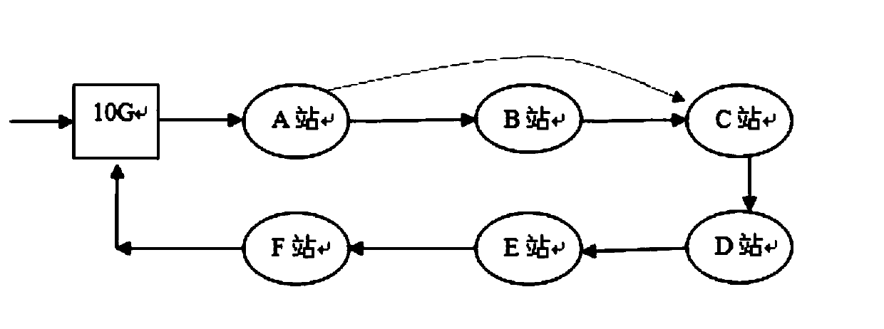
[0025] The embodiment of the present invention first proposes a route switching method to perform route switching when the base station in the ring optical transmission network is powered off.
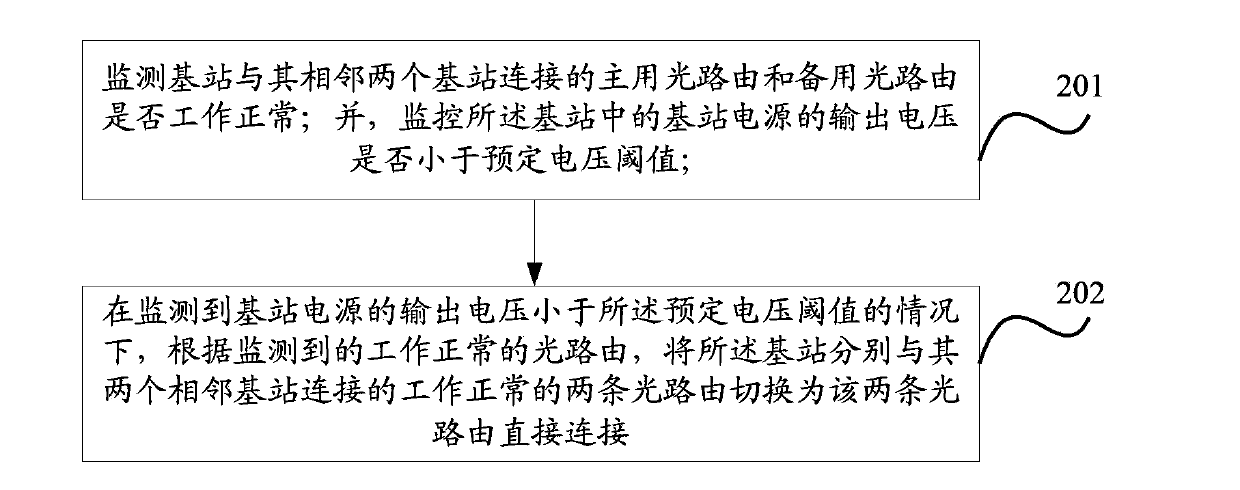
[0026] figure 2 shows the workflow of the route switching method applied to the ring optical transmission network provided by the embodiment of the present invention, the method includes:
[0027] Step 201, monitoring whether the main optical route and the backup optical route connected to the base station and its two adjacent base stations are working normally; and monitoring whether the output voltage of the base station power supply in the base station is less than a predetermined voltage threshold;
[0028] Specifically, the operation of monitoring whether the optical routing works normally is: monitoring whether the power of the optical signal sent and received by the base station is normal;
[0029] Specifically, the predetermined voltage threshold is greater than or equal to t...
Embodiment 2
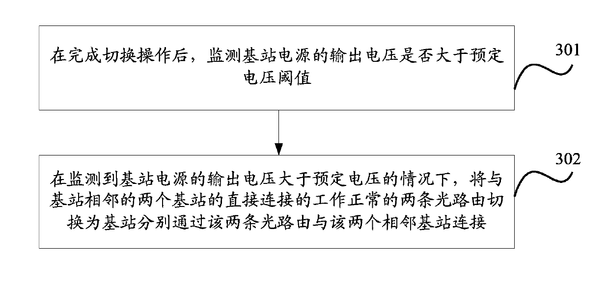
[0074] The embodiment of the present invention also provides a processing solution for a base station to passively switch routes according to an instruction from a remote terminal.
[0075] Figure 6 It shows the working process of the route switching method applied to the ring optical transmission network provided by the embodiment of the present invention, as shown in Figure 6 As shown, the method includes:
[0076] Step 601, receiving a first switching instruction or a second switching instruction from a remote terminal, where the first switching instruction or the second switching instruction includes authority information;
[0077] Step 602, authenticating the authority information in the first switching instruction or the second switching instruction;
[0078] Step 603: In the case that the authority information in the first switching instruction passes the authentication, switch the two normal optical routes connected to the base station and its two neighboring base ...
PUM
 Abstract
Description
Claims
Application Information
 - R&D Engineer
- R&D Manager
- IP Professional
- Industry Leading Data Capabilities
- Powerful AI technology
- Patent DNA Extraction
Browse by: Latest US Patents, China's latest patents, Technical Efficacy Thesaurus, Application Domain, Technology Topic, Popular Technical Reports.
© 2024 PatSnap. All rights reserved.Legal|Privacy policy|Modern Slavery Act Transparency Statement|Sitemap|About US| Contact US: help@patsnap.com