
Receptacle connector

A technology for socket connectors and plug connectors, which is applied in the direction of connection, parts of connecting devices, fixed/insulated contact members, etc., can solve the problems of inability to shorten the depth direction and length, etc.

Inactive Publication Date: 2014-06-18
SMK CO LTD
View PDF3 Cites 6 Cited by
  • Summary
  • Abstract
  • Description
  • Claims
  • Application Information

AI Technical Summary

Problems solved by technology

[0017] However, the above-mentioned conventional receptacle connector 130 exposes the additional contacts 136 to the rear of the contact portion 123a, so the length of the receptacle connector 130 in the front-rear direction along the insertion direction of the USB plug becomes longer. USB standard, a receptacle connector that makes the appearance miniaturized when viewed from the insertion direction, and its depth direction cannot be shortened
[0018] Also, the extension plug connected to the receptacle connector 130 exposes a plurality of additional plug terminals to the rear (front end direction) of the five plug terminals surrounded by the fitting cylinder, and therefore, similarly, the length along the insertion direction cannot be shortened. At the same time, when it is not connected to the socket connector 130, the additional plug terminal is exposed to the rear of the fitting cylinder, so there is a risk of damage by external force, or the electronic components connected by the plug terminal will be damaged by static electricity due to touch by fingers, etc.

Method used


Image

  • Receptacle connector
  • Receptacle connector
  • Receptacle connector

Examples


Embodiment Construction

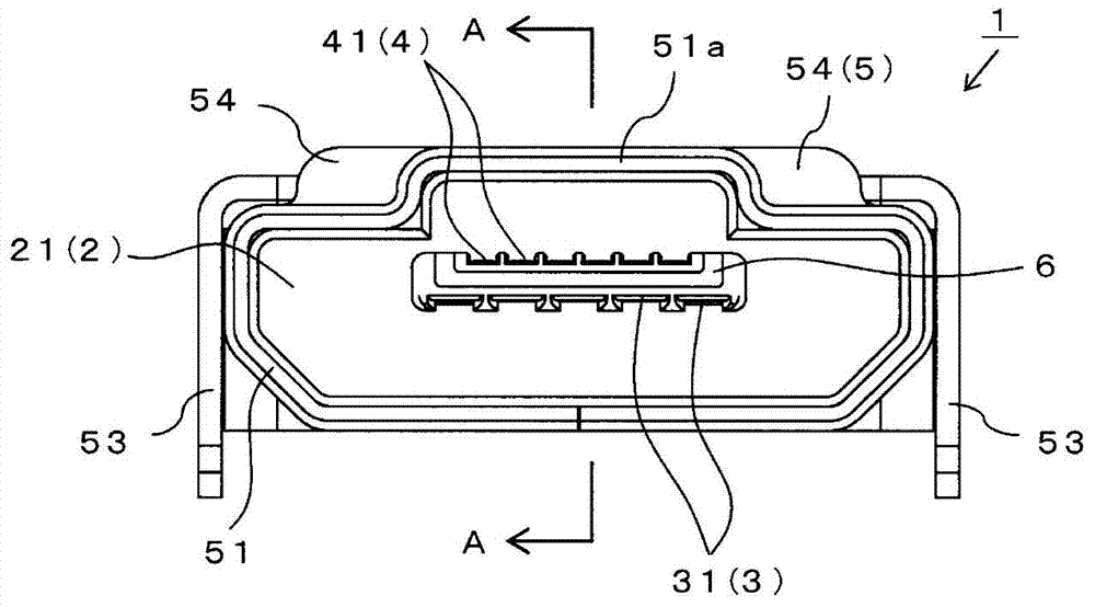
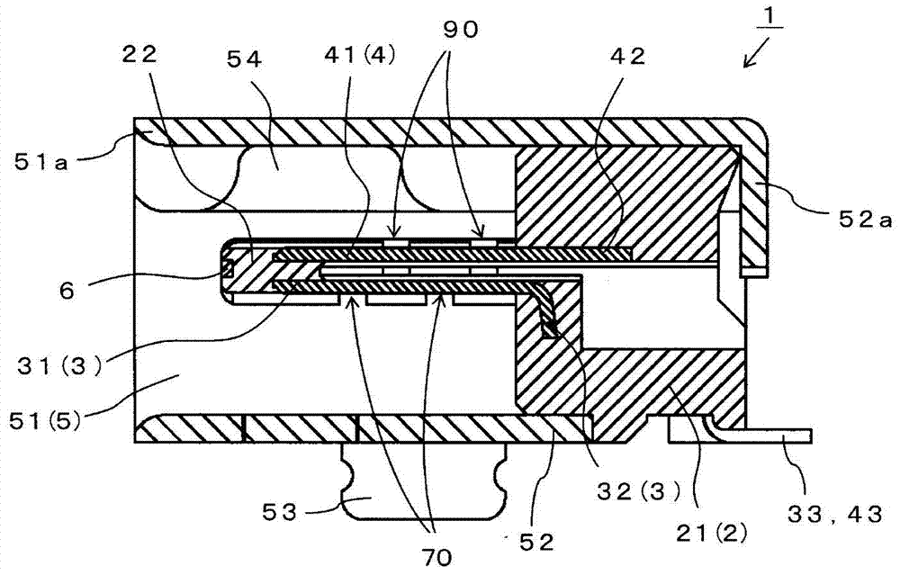
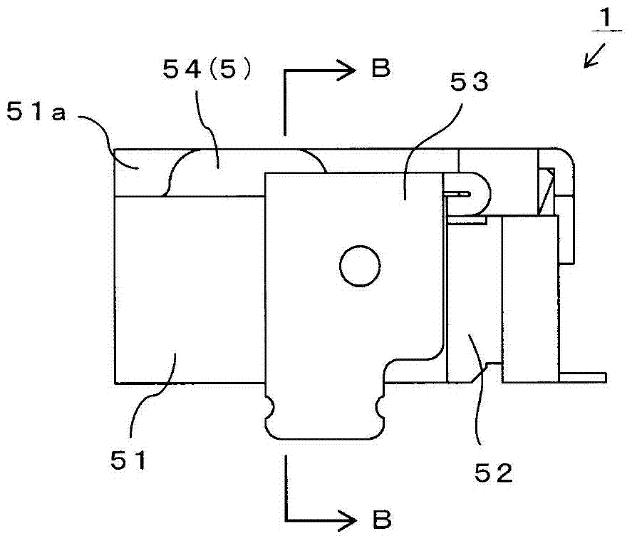
[0091] Below, refer to Figure 1 to Figure 13 The receptacle connector 1 according to one embodiment of the present invention will be described in detail. In the following embodiments, various limitations are made on constituent elements, types, combinations, shapes, relative arrangements, etc., but these are merely examples, and the present invention is not limited thereto.

[0092] In the following description of each part of the receptacle connector 1, the insertion direction of the USB plug 110 or the extension plug 100 (in figure 1 In the paper, the depth direction of the paper) is taken as the rear, the front side is taken as the front, and the figure 1 Each of the directions shown will be described as up, down, left, and right directions.

[0093] Receptacle connector 1 is in accordance with the Micro-USB specification, and is equivalent to Figure 13 The USB plug 110 of the first plug connector shown is connected, meanwhile, it can also be connected with the equiva...


PUM


Abstract

The invention relates to a receptacle connector comprising a USB plug with a Micro-USB specification and without increasing insertion length and capable of being connected even with an expanding plugt on a plug terminal. Space that does not interfere with an engagement protrusion of a first plug connector is maintained at the top of the interior of a chassis that attaches the receptacle connector, and so the inner peak surface of a fitting cylinder sandwiched by a pair of engagement receiving sections is formed curving upwards and a second plug connector disposed with the addition of a plurality of third plug terminals above a second plug terminal can be inserted. When the first plug connector is inserted, a first plug terminal contacts a first contact exposed at the bottom surface of a support plate, and when the second plug connector is inserted, the second plug terminal and third plug terminals contact the first contact and a second contact.

Description

[0001] technology area [0002] The present invention relates to a socket connector (receptacle connector) that can be connected to various types of plug connectors with different positions of plug terminals. Receptacle connector for extension plug connection of plug terminals. Background technique [0003] The Micro-USB specification (USB2.0 High Speed) is one of the USB (Universal Serial Bus, Universal Serial Bus) specifications used to connect host computers such as computers and their peripheral devices. According to the standard set by the interface, the receptacle connector connected to the USB plug according to the Micro-USB standard is generally used as a connector for connecting electronic products such as personal computers, mobile phones, digital cameras and their peripheral devices. [0004] As an example of the USB plug conforming to the Micro-USB standard, Figure 13 It shows the USB plug 110 described in Patent Document 1. On the rear surface of the insulating ...

Claims


Application Information

Patent Timeline
Patent Type & Authority Applications(China)
IPC IPC(8): H01R12/71H01R13/40
CPCH01R13/6581H01R12/724H01R12/75H01R27/00
Inventor 义浦康夫小野直之
Owner SMK CO LTD
Learn More