
Variable intake manifold for internal combustion engine and variable air intake device using the same

A technology for internal combustion engines and intake manifolds, applied in the direction of internal combustion piston engines, combustion engines, mechanical equipment, etc., can solve problems such as inability to be strong, and achieve the effects of preventing incomplete combustion, improving intake efficiency, and properly correcting assembly errors

Inactive Publication Date: 2014-06-18
HYUNDAI MOTOR CO LTD +1
View PDF6 Cites 2 Cited by
  • Summary
  • Abstract
  • Description
  • Claims
  • Application Information

AI Technical Summary

Problems solved by technology

[0014] However, it has been suggested that both strong tumble and strong swirl cannot be obtained in the above-mentioned conventional variable air intake device

Method used


Image

  • Variable intake manifold for internal combustion engine and variable air intake device using the same
  • Variable intake manifold for internal combustion engine and variable air intake device using the same

Examples


Embodiment Construction

[0038] Reference will now be made in detail to various embodiments of the invention, examples of which are illustrated in the drawings and described below. While the invention has been described in conjunction with exemplary embodiments, it will be understood that present description is not intended to limit the invention to those exemplary embodiments. On the contrary, the invention is intended to cover not only the exemplary embodiments, but also various alternatives, modifications, equivalents and other alternatives, modifications, equivalents and other alternatives, which may be included within the spirit and scope of the invention as defined by the appended claims. In the implementation plan.

[0039] Exemplary embodiments of the present invention will be described in detail below with reference to the accompanying drawings.

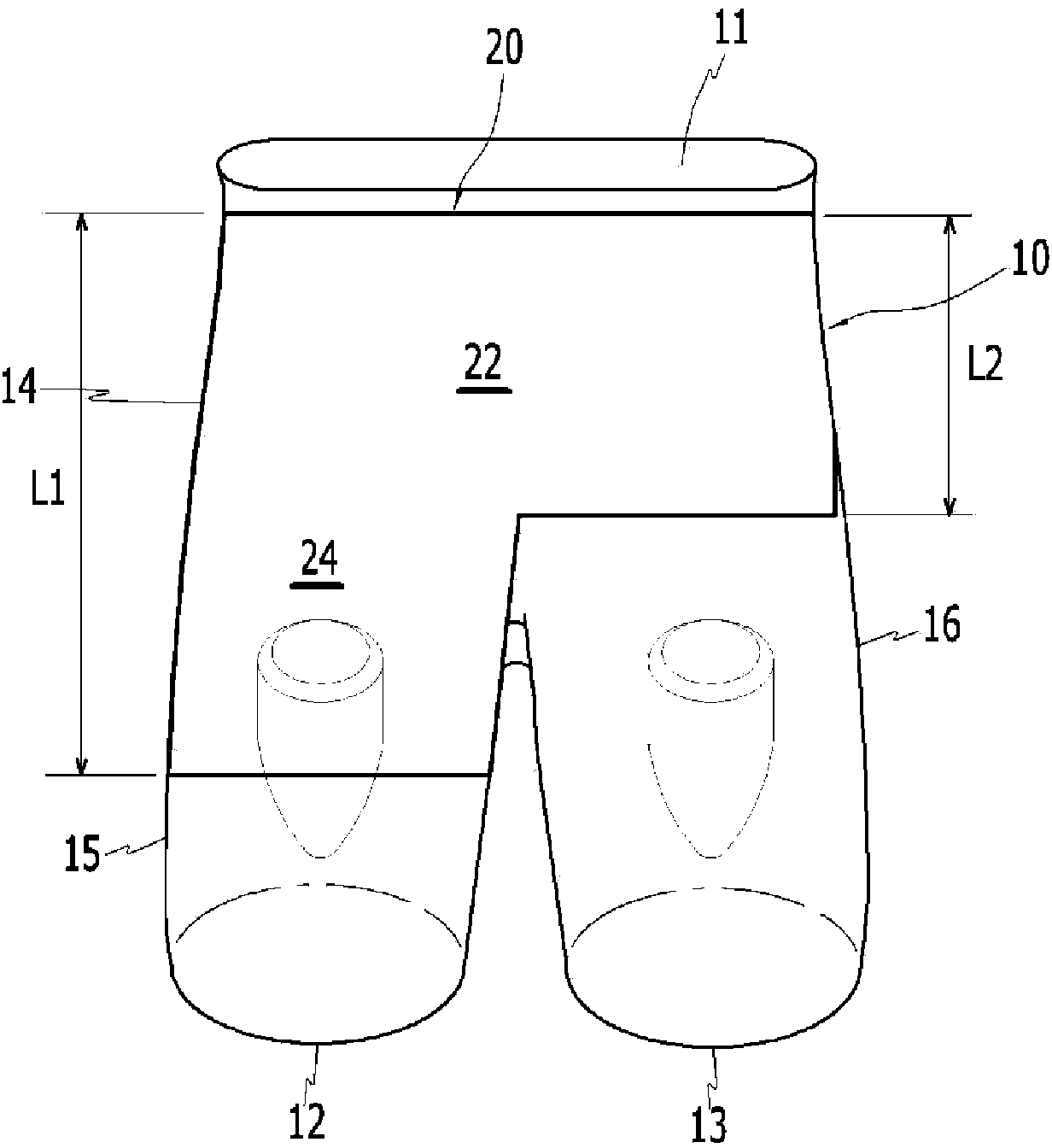
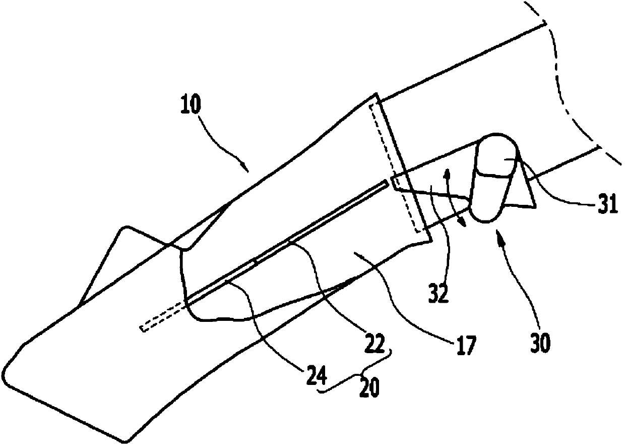
[0040] refer to figure 1 , The variable intake manifold 10 according to the exemplary embodiment of the present invention includes an inlet 11 f...


PUM


Abstract

A variable intake manifold apparatus for an internal combustion engine, may include an inlet drawing in outside air and being connected to a main passage, first and second outlets branched from the main passage and fluid-connected to the inlet through the main passage and releasing the outside air drawn through the main passage through the first and second outlets, and a partition dividing the main passage and one of the first and second intake passages.

Description

[0001] Cross References to Related Applications [0002] This application claims priority from Korean Patent Application No. 10-2012-0147808 filed on December 17, 2012, the entire contents of which are hereby incorporated by reference for all purposes. technical field [0003] The present invention relates to a variable intake manifold for an internal combustion engine and a variable intake device using the variable intake manifold, more particularly to such a variable intake manifold for an internal combustion engine and a variable intake device, which enhances the tumble and swirl of the intake air. Background technique [0004] Typically, combustion chambers are formed in internal combustion engines for direct injection of fuel by coupling a cylinder head to a cylinder block in which a piston is configured to reciprocate to compress or expand the combustion chamber and change its volume. [0005] An intake port for introducing air into the combustion chamber and an exhau...

Claims


Application Information

Patent Timeline
Patent Type & Authority Applications(China)
IPC IPC(8): F02B31/04
CPCF02B31/04F02B31/06Y02T10/12F02M35/104F02B27/02
Inventor 韩东熙韩胜国林贤俊秋东昊金润柱金知湖任爀朴钟一
Owner HYUNDAI MOTOR CO LTD
Learn More