
Electric pole centralizer

A technology of centralizers and electric poles, applied in building types, buildings, towers, etc., can solve the problems of shovel digging difficulty, low efficiency, high labor intensity, etc., to reduce the price and operation difficulty, simple structure, and enhance versatility Effect

Inactive Publication Date: 2014-06-18
STATE GRID SHANDONG ELECTRIC POWER COMPANY WEIFANG POWER SUPPLY +1
View PDF10 Cites 147 Cited by
  • Summary
  • Abstract
  • Description
  • Claims
  • Application Information

AI Technical Summary

Problems solved by technology

If the pole tilts during this process, it will be very difficult to straighten the pole. The reasons are as follows: When the pole is straightened, it must occupy the ground space on the upright side. Then, 1. If the earth and rocks in this space are not cleared, then It is necessary to forcefully squeeze the soil and rock, and the required external force is extremely large. Generally, construction machinery, such as cranes, bulldozers, etc., must be used. If the soil and rocks in the space are completed by manually operating the shovel, firstly, the soil and rocks on the surface are relatively hard, and it is difficult to dig with the shovel. Secondly, for the convenience of digging with the shovel, a relatively large amount of upper layer of soil and rock must be dug out before the lower layer of soil and rock can be deeply excavated. Excavating the space on the upright side of the pole is conical with a large upper end and a smaller lower end, so it is time-consuming, labor-intensive, and inefficient. If it is completed by construction machinery such as excavators, there will be problems due to terrain, traffic restrictions, and unbalanced erection costs. high problem
[0005] Chinese patent Nos. 201220200863.X and 201220222955.8 utility model patents disclose two positive rod devices, these positive rod devices use the jacking force of the hydraulic lifting device (jack) to carry out strong righting, and have a certain righting effect, but there are The following disadvantages: 1. It does not have the function of cleaning up the soil and rocks on the positive side of the pole. Manual excavation or construction machinery assistance is needed to realize the fast and smooth straightening of the pole; The fixing effect of the pole submerged in the ground is much greater than that of the straight nails submerged in the ground, and the soil becomes hard. If the jack is used to straighten the pole without excavating the earth and rocks on the upright side of the pole, only the bottom of the jack will slip with the ground and cause Failed to straighten; 3. The two positive rod devices used are locked with the electric pole through the hoop (clip), and the force analysis of the hoop (clip) shows that the force of the hoop (clip) can be divided by the force of the jack. It is the upward force along the pole and the force in the righting direction of the pole. The force in the righting direction of the pole has the effect of righting the pole. However, since the poles are all conical columns with thinner upper ends and thicker ends, the The upward force will push the hoop (clip) to the thinner end of the pole. Once the upward force along the pole is greater than the friction between the inner wall of the hoop (clip) and the outer wall of the pole, the hoop (clip) will ) will inevitably slip up along the pole, resulting in the failure of righting; 4. By pulling hard, it has a certain effect on those new poles that are newly put into use with a stable structure, but for those old poles that have been used for many years, It is easy to break the pole during the righting process

Method used


Image

  • Electric pole centralizer
  • Electric pole centralizer
  • Electric pole centralizer

Examples


Embodiment Construction

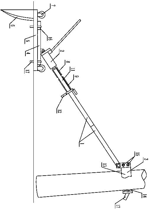
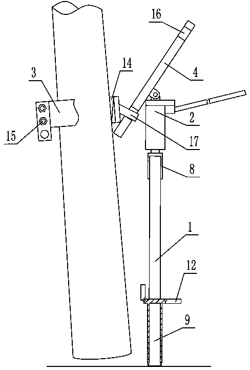
[0037] As shown in the figure, the pole centralizer includes a plurality of multifunctional components, and each multifunctional component is connected through different combinations or assembly methods, thereby realizing different functions. The so-called multifunctional component means that the component has more than one function or function in the pole centralizer, and different combinations of each multifunctional component can realize different functions. Specifically, the pole centralizer mainly includes a clamp 3 , a support rod 1 , a jack 2 and a base 5 connected in sequence. In the pole centralizer, the clamp 3, the support rod 1, the jack 2 and the base 5 all belong to multifunctional components. The clamp 3, the support rod 1, the jack 2 and the base 5 can realize different functions through different combinations or connection methods. In this electric pole centralizer, the different functions realized by the clamp 3, the support rod 1, the jack 2 and the base 5 ...


PUM


Abstract

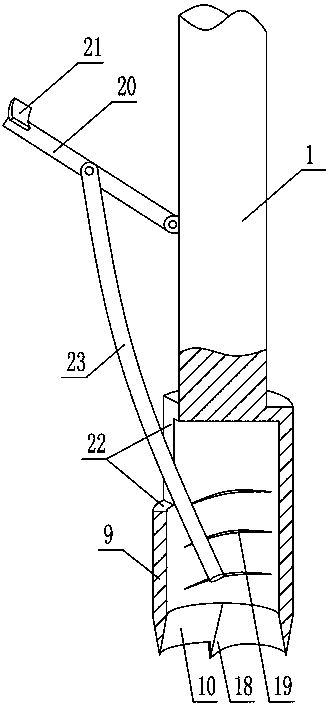
The invention discloses an electric pole centralizer. The electric pole centralizer comprises a clamp hoop connected onto the top of a jack by a support rod; the bottom of the jack is hinged to the bottom plate; the electric pole centralizer also comprises a base; a withdrawal stop plate capable of being embedded underground is fixedly arranged at the top surface of the base; idler wheels are arranged on the base; clamping parts matched with the bottom plate are arranged at two side surfaces of the base and the outside surface of the clamp hoop; a sleeve is fixedly and coaxially arranged at the top of the jack; the lower end of the support rod is provided with a tube drum; iron pillars are inserted into the tube sleeve and the sleeve; an annular edge is arranged at the lower end of the tube drum; a cross rod is fixedly arranged at the upper end of the tube drum; the clamp hoop is formed by hinging two semi rings together; the two semi rings are locked together by a locking bolt. A detachable hinging part is arranged at the upper ends of the clamp hoop and the support rod. The electric pole centralizer adopting the structure is reasonable in structure, soil and stones at the positive position side of an electric pole can be easily excavated, the electric pole can be smoothly centralized, the fixing is firm, the transfer is convenient, the electric pole is prevented from being broken and the electric pole centralizer is particularly suitable for centralizing the electric pole used for years.

Description

technical field [0001] The invention relates to a pole centralizer. Background technique [0002] Low-voltage overhead lines are lines used by residents and agricultural production. Most low-voltage overhead lines are supported by cement poles. When the cement pole is erected, it is generally hoisted and straightened by a crane, and the erection is very simple. Because the soil is soft when the poles are first installed, the poles during erection often tilt. This leads to the fact that the crane can only erect the second pole after one pole is completely erected, so the erection efficiency is low. For example, the pole centralizer whose Chinese patent number is 201320216893.4 is designed for hoisting electric poles. [0003] After the cement pole is installed, due to factors such as seasonal changes, geological conditions, and operating time, the cement pole is often skewed, which seriously threatens the normal operation of the power distribution line, so it is necessary ...

Claims


Application Information

Patent Timeline
IPC IPC(8): E04H12/20E02D35/00
Inventor 李玉亮蔡涵宇杨志荣徐学栋齐光春张海波王海妍赵杉刘宝来李道林王海升
Owner STATE GRID SHANDONG ELECTRIC POWER COMPANY WEIFANG POWER SUPPLY
Learn More