Remote manual driveshaft center bearing height adjustment mechanisms

A technology of height adjustment mechanism and drive shaft, which is applied in control devices, vehicle components, transportation and packaging, etc., can solve the problems of difficult access for users and ineffective position of the drive shaft, and achieve the effect of improving ride comfort and maneuvering flexibility

Active Publication Date: 2014-06-18
FORD GLOBAL TECH LLC
View PDF5 Cites 0 Cited by
  • Summary
  • Abstract
  • Description
  • Claims
  • Application Information

AI Technical Summary

Problems solved by technology

However, the pre-set propshaft position is less effective when the vehicle is operated beyond custom use
[0006] Finally, an adjustable bracket for the drive shaft used in maintenance or service applications allows adjustments to be made by accessing the underside of the vehicle; however, this is inaccessible to most users

Method used


Image

  • Remote manual driveshaft center bearing height adjustment mechanisms
  • Remote manual driveshaft center bearing height adjustment mechanisms
  • Remote manual driveshaft center bearing height adjustment mechanisms

Examples


Embodiment Construction

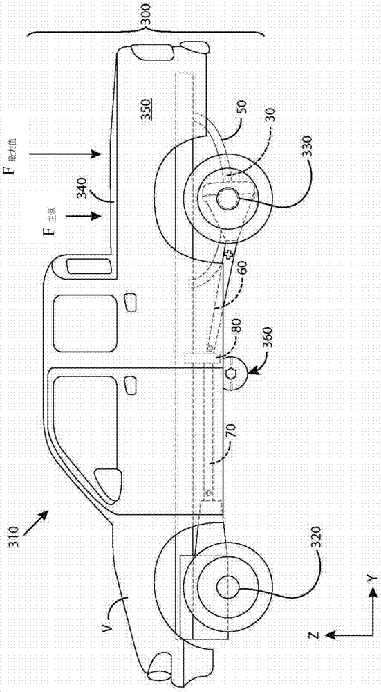
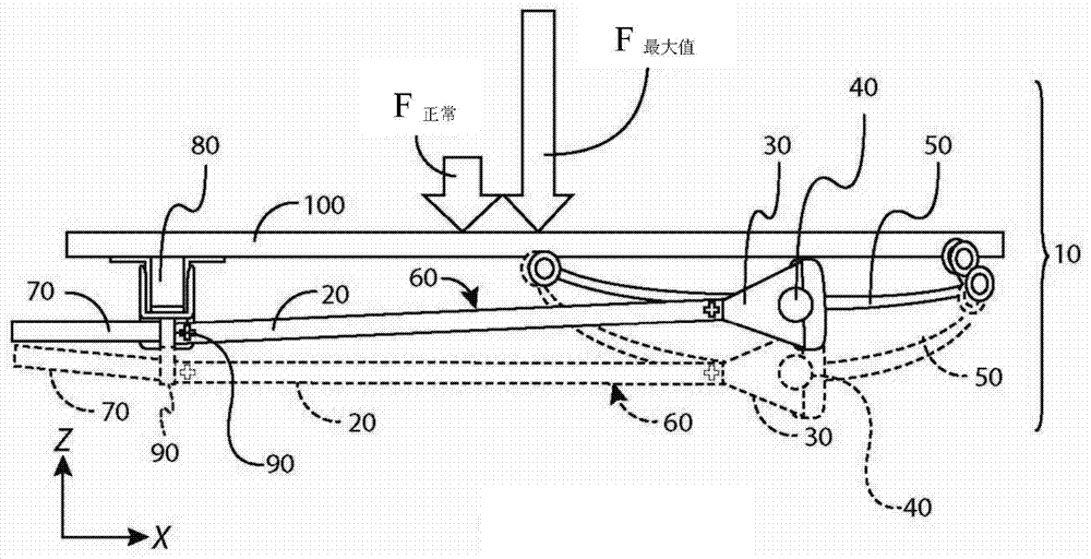
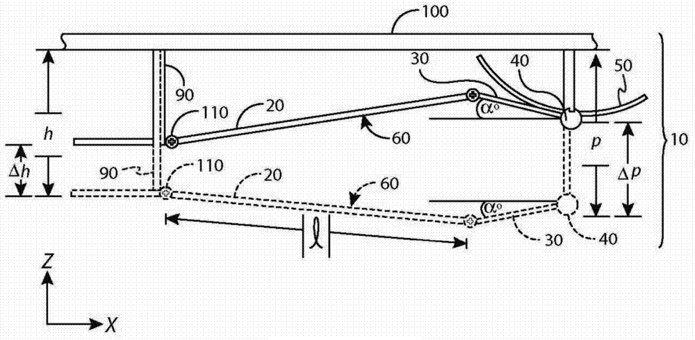
[0024] Referring to the drawings, there is shown an exemplary height adjustment mechanism (or "HAM") for a vehicle propshaft, wherein like features represent examples of like or corresponding parts throughout the several views. The illustrated HAM provides a propshaft manual selector set based on vehicle load conditions. The driver may actuate a manual user input device (eg, a lever) to select the height of the drive shaft center bearing bracket. The predetermined positions provide optimum driveline angles for specific load conditions. The manual user input device is positioned remotely from the propeller shaft and the mounting device for the propeller shaft. The manual user input device is thus remotely located relative to the propshaft mounting arrangement while being convenient for the driver to use. For example, in the illustrated embodiment, the manual user input device is located on the side of the vehicle, bonded to the body sheet metal at knee height.

[0025] The i...


PUM


Abstract

A manual height-adjustment mechanism (MHAM) for a vehicle driveshaft, includes a movable bracket assembly configured to attach to the driveshaft and a vehicle cross-member; and a user input device remotely located with respect to the movable bracket assembly, configured to control the movable bracket assembly.

Description

technical field [0001] The present invention relates to height adjustment mechanisms for vehicle drive shafts. Background technique [0002] The vehicle propshaft connects the transmission to the remote axle. This is commonly found in rear-wheel drive (RWD) and all-wheel drive (AWD) vehicles. During normal driving, the drive shaft can move vertically relative to the vehicle frame. For example, if figure 1 and figure 2 As shown in , the angular configuration of the front of the drive shaft alternates in different directions depending on the loading conditions of the vehicle. However, propshaft components are designed to operate within a preferred range of angles. Many vehicles with rear- or all-wheel drive systems are designed for standard payloads so that the propshafts are angled in the preferred position. Known suspension cushioning or performance characteristics also contribute to this. Angle fluctuations outside of design criteria can produce objectionable vehicl...

Claims


Application Information

Patent Timeline
Patent Type & Authority Applications(China)
IPC IPC(8): B60K17/22
CPCB60K17/22B60K17/24
Inventor 贾梅尔·伯兹特比尔·伊克斯阿里奥斯托·曼奇尼
Owner FORD GLOBAL TECH LLC
Why Eureka
Try Eureka