
Mould pressing device and method of composite material

A composite material and molding technology, which is applied in the field of composite material molding equipment, can solve the problems of low product yield, prone to bubbles on the product surface, poor exhaust, etc., and achieve the effect of high gloss on the surface

Inactive Publication Date: 2014-06-18
GUANGDONG JANUS SMART GRP CO LTD
View PDF5 Cites 7 Cited by
  • Summary
  • Abstract
  • Description
  • Claims
  • Application Information

AI Technical Summary

Problems solved by technology

Due to the poor exhaust in the existing compression molding process, there is a problem of trapped air, and air bubbles are easy to appear on the surface of the product, leaving many pinholes. These pinholes cannot be filled, which seriously affects the surface effect of the shell of consumer electronics products. , leading to low product yield

Method used


Image

  • Mould pressing device and method of composite material
  • Mould pressing device and method of composite material
  • Mould pressing device and method of composite material

Examples


example 1

[0047] 1) The fiber prepreg is cut, and the cutting direction is 45°. It is cut according to the product specification, and the edge part is 0.8cm longer than the product specification. The interlayer arrangement of the fiber prepreg fabric is staggered, which is a layer of twill bidirectional weave fabric, a layer of unidirectional fabric and a layer of plain weave bidirectional fabric, and the thickness of the fabric is 0.6mm.

[0048] 2) Clean the mold with carbon fiber cleaning agent and mold release agent, put it on the hot plate and heat it to 60°C, the detergent will evaporate, then apply the mold release agent, dry for 10 seconds, a film will form on the surface of the mold, and then spread cloth, flatten the cloth.

[0049] 3) Heating and pressing once, the temperature rises to 80°C, and the pressure rises to 2kgf / cm 2 .

[0050] 4) Constant temperature for 100s, control the opening and closing of the hot platen for exhausting, the number of exhausting times is 4 ti...

example 2

[0057] 1) The fiber prepreg is cut, and the cutting direction is 90°. It is cut according to the product specification, and the edge part is 0.8cm longer than the product specification. The layers of fiber prepreg are staggered, and the arrangement is 3 layers of twill bidirectional weave fabric + 5 layers of unidirectional fabric, and the thickness of the fabric is 1.25mm.

[0058] 2) Clean the mold with carbon fiber cleaning agent and mold release agent, put it on the hot plate and heat it to 60°C, the detergent will evaporate, then apply the mold release agent, dry for 10 seconds, a film will form on the surface of the mold, and then spread cloth, flatten the cloth.

[0059] 3) Heating and pressing once, the temperature rises to 85°C, and the pressure rises to 2kgf / cm 2 ,

[0060] 4) When the mold reaches the temperature, keep the temperature constant for 120s, control the opening and closing of the hot platen for exhausting, the number of exhausting times is 8 times, the...


PUM

PropertyMeasurementUnit
widthaaaaaaaaaa
widthaaaaaaaaaa
depthaaaaaaaaaa

Abstract

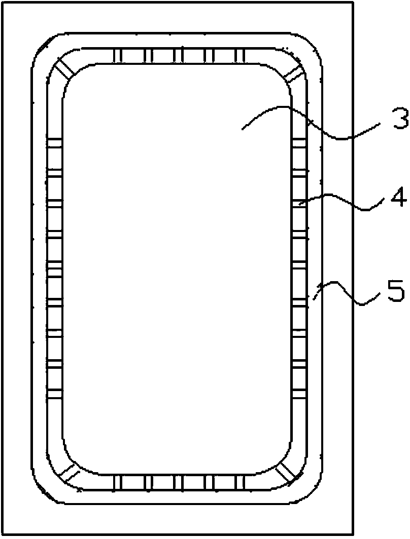
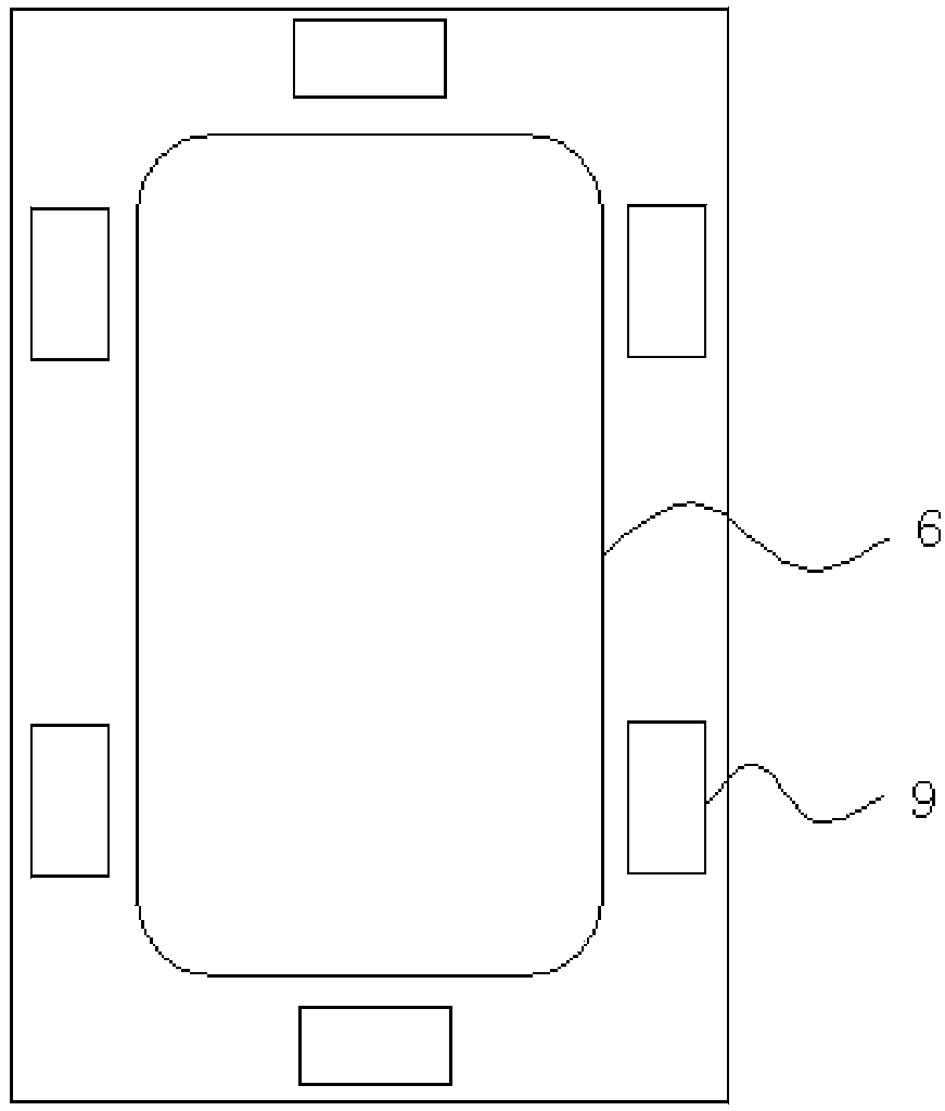
The invention provides a mould pressing device of a composite material. The mould pressing device of the composite material comprises an upper hot press plate, a concave mould, a convex mould and a lower hot press plate, wherein the concave mould comprises a middle sunken area and a platform area surrounding the sunken area; the convex mould comprises a middle protruded area and a platform area surrounding the protruded area; at least one exhaust slot is formed in an adjacent area of the platform area and the sunken area of the convex mould. A mould pressing method of the composite material, which is further provided by the invention, comprises a process of controlling the upper hot press plate and the lower hot press plate to tight fold the concave mould and the convex mould so as to heat and pressurize materials in a mould, wherein air in the mould is discharged through the exhaust slot in the heating and pressurizing process. According to the mould pressing device and the mould pressing method of the composite material, which are provided by the invention, the problem of air trapping in a mould pressing process can be effectively solved, and the surface effect of product shells is improved.

Description

technical field [0001] The invention relates to a molding equipment and method for composite materials. Background technique [0002] Composite materials are used as shell materials of consumer products, which can make the shell materials not only have the elegant and strong characteristics of aluminum-magnesium alloys, but also have the high plasticity of PC / ABS engineering plastics. The appearance is similar to plastics, but the strength and thermal conductivity are better than ordinary PC / ABS. ABS plastic. Existing molding methods for composite materials include hand lay-up molding, lamination molding, RTM method, extrusion method, compression molding, winding molding, etc. Compression molding is a relatively common molding method, for example, fiber materials and thermosetting resins are passed through Compression molding results in a fiber composite shell material. Due to the poor exhaust in the existing compression molding process, there is a problem of trapped air, ...

Claims


Application Information

Patent Timeline
Patent Type & Authority Applications(China)
IPC IPC(8): B29C70/34B29C70/54B29C33/10
CPCB29C33/10B29C70/345B29C70/54
Inventor 周忠群王长明谢守德
Owner GUANGDONG JANUS SMART GRP CO LTD
Learn More